SimSolid performs meshless structural
analysis that works on full featured parts and assemblies, is tolerant of
geometric imperfections, and runs in seconds to minutes. In this tutorial,
you will do the following:
Learn how to create welds from solids, group welds, master welds, and welds
from lines/edges.
Model Description
The following files are needed for this tutorial:
Foot Bridge_solid_parts.x_b
SeamWeldLines.xml
Figure 1.
Import Geometry
Open a new SimSolid session.
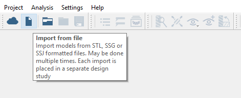
Click the (Import from file) icon.
Figure 2.
In the Open geometry files dialog, choose
Foot Bridge_solid_parts.x_b.
Click Open.
The assembly will load in the modeling window.
The
Automatic connections dialog opens.
Click Cancel to close the dialog.
Create Seam Welds from Solids
Convert solids into seam welds.
In the Project Tree, select the
Connections workbench.
On the toolbar, click > Create new seam welds.
In the dialog, select the Weld from solid tab.
Set Section size to 5.
Figure 3.
Section size defines the lengths from the toe to the root of the weld. Figure 4.
Select parts in one of the following ways:
In the Project Tree, expand the
Assembly branch and select the highlighted parts
shown in Figure 5. Figure 5.
In the Create seam welds dialog, select the
Find parts by keyword radio button and type
Weld. Then click Hide
parts.
Select parts in the modeling window.
Selected solid parts are highlighted in the modeling window. Figure 6.
Click Find parts.
In the dialog, a preview of the found welds is shown. Figure 7.
Click OK.
Solid welds are created by suppressing the solid parts from which they
were created. Suppressed solid parts are removed from the Project Tree. Figure 8.
Create Welds Using Group Welds
Use the Group Welds option to create seam welds.
In the dialog, switch to the Group weld tab.
Set Section size to 5 mm.
Set Minimum length to 12 mm.
In the modeling window, hide the walkway part of the
bridge and then select the rest of the parts.
Figure 9.
Click Find welds.
A preview of the found welds is shown.Figure 10.
Click OK.
Figure 11.
Review Connections and Delete Seam Welds
Review part connections and delete seam welds associated with a part.
In the modeling window, select the arch shown in orange
in Figure 12.
Right-click on the part and select Review part
connections in the context menu.
Figure 12.
All the seam welds associated with the part are listed in a
dialog.
Select all connections in the dialog.
Click Delete.
Figure 13.
Click Close to dismiss the dialog.
Create Welds Using Master Welds
Use the Master Welds option to create seam welds.
In the dialog, switch to the Master weld tab.
Set Section size to 5 mm.
Set Minimum length to 12 mm.
Activate the Master part radio button.
In the modeling window, select the arch.
In the modeling window, select the parts shown in
orange in Figure 14.
Figure 14.
Click Find welds.
A preview of found welds is shown. Figure 15.
Click OK.
Create Welds Using Lines/Edges
Use lines/edges to create seam welds.
In the modeling window, zoom in on the part shown in
Figure 16.
Figure 16.
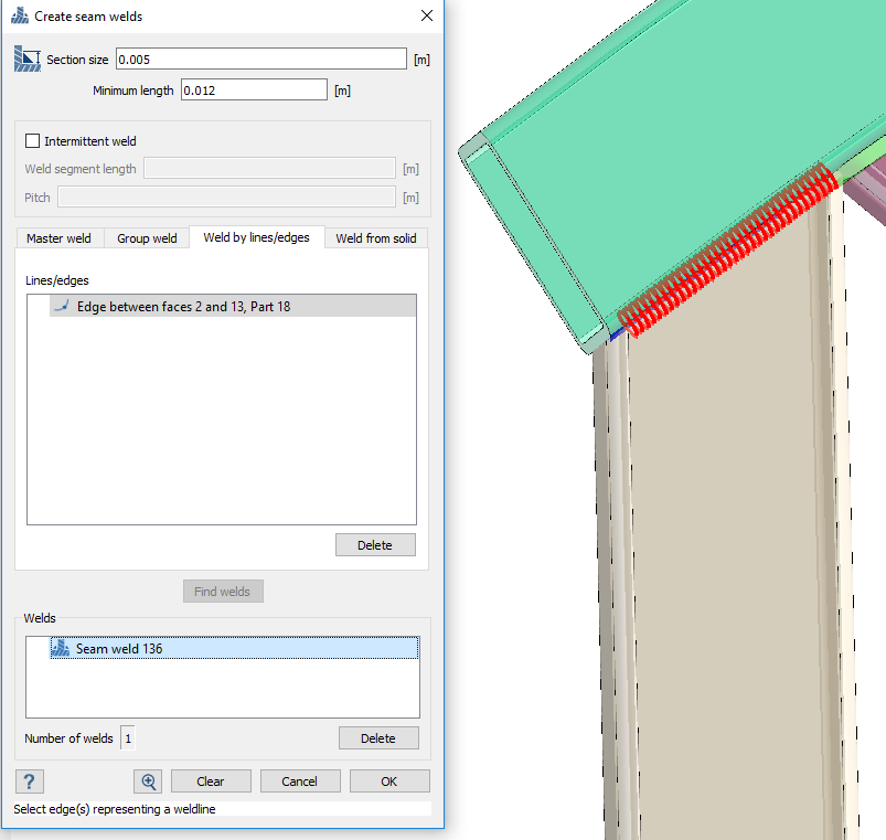
In the dialog, switch to the Weld by lines/edges
tab.
Set Section size to 0.005.
Set Minimum length to 0.012.
In the modeling window, select the edge shown in pink
in Figure 17.
Figure 17.
Click Find welds.
A preview of the found welds is shown.Figure 18.
Click OK.
Figure 19.
Repeat steps 2
through 7 to
create welds at the other edges of this part.
Review Seam Welds
Review seam welds and delete welds created from solids.
Right-click on the walkway and select Review part
connections in the context menu.
Figure 20.
All connections for the selected part are listed in a
dialog.
In the dialog, select all seam welds.
Figure 21.
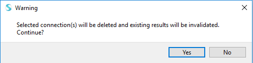
Click Delete.
In the first Warning dialog, click
Yes.
Figure 22.
In the second Warning dialog, click Delete
parts.
This will delete the parts from which the welds were created. Figure 23.
Create Seam Welds from Imported Lines
Import lines and create seam welds from those lines.
On the Connections toolbar, click (Seam welds).
Select the Weld by lines/edges tab.
Click Import.
Figure 24.
In the File explorer, select SeamWeldLines.xml and click
Open.
Imported lines are listed in the Lines/Edges section of the dialog and
drawn in the modeling window. Figure 25.
Click to look more closely at the line.
The selected line is highlighted in red.
Click Find welds.
Review the welds and click OK
to accept them.
Figure 26.
Add Material
Add material to seam welds.
On the Connections toolbar, click (Seam welds) > Apply material to seam welds.
Figure 27.
In the Material database, select General Materials > Steel.
Figure 28.
Click Apply to all welds.
Click OK.
If material is not assigned to the seam weld by user, SimSolid automatically assigns material properties of the
adjacent part with strongest material at the time of solving.

 (Import from file) icon.
 > Create new seam welds.


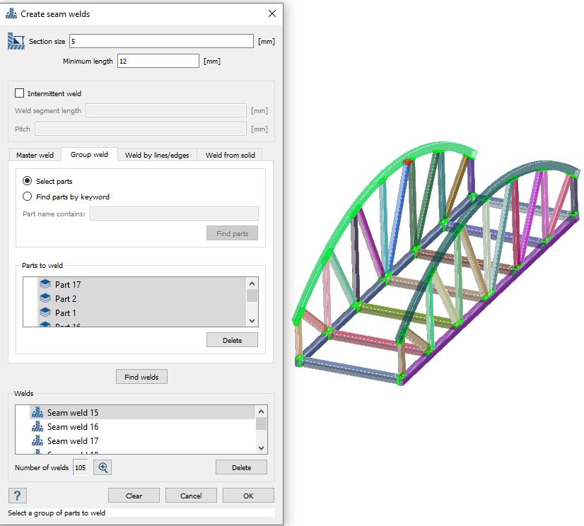 Figure 10.
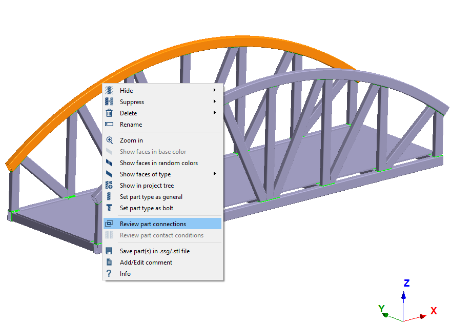 Figure 12. All the seam welds associated with the part are listed in a dialog.
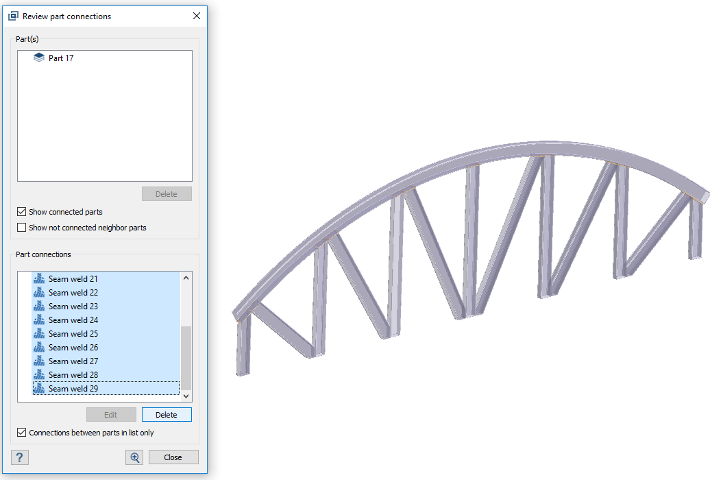 Figure 13.


 to look more closely at the line.
The selected line is highlighted in red.
to look more closely at the line.
The selected line is highlighted in red.

