MV-1030: Create a System Definition Using the MotionView GUI
In this tutorial you will learn how to create systems using the MotionView graphic user interface, export a system definition to a file, and instantiate a saved definition in a model.
Create a System Instance
In this step, you will create a system instance.
-
Open the Add System/Assembly dialog in one of the
following ways:
- In the Project Browser, right-click on Model and select .
- On the Container Entity toolbar, right-click the
 (System/Assembly panel) button.
-
Click OK.
This will add the Pendulum system
 to the model and display the
system's panel.
to the model and display the
system's panel.
Add Attachments to the System
In this step you will create two attachments for the Pendulum system.
-
Use steps 1
through 4 to
create a second attachment.
-
From the drop-down menu, select Body.
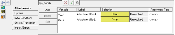
Figure 1.Note: These attachments will be used to attach this system to other model entities. Notice that both are currently Unresolved, meaning they are not yet referring to another entity in the model.
-
From the drop-down menu, select Body.
-
Double-click the
 collector.
-
In the Select a Point dialog, click Global Origin.
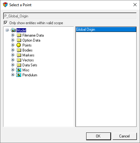
Figure 2. -
Double-click the
 collector.
Add a Point to the System
In this step you will add a point to the Pendulum system.
-
Open the Add Point or PointPair dialog in one of the
following ways:
- Right-click on Pendulum and select .
- On the Reference Entity toolbar, right-click the
 (Points) icon.
-
In the dialog, specify the Label as Mass CG and the
Variable as p_cg. Verify that Type is set to
Single.
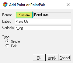
Figure 3. -
From the Properties tab, click the X Coordinate field.
Then click the
 button.
This will display the Expression Builder.
button.
This will display the Expression Builder. -
Click the Add button.
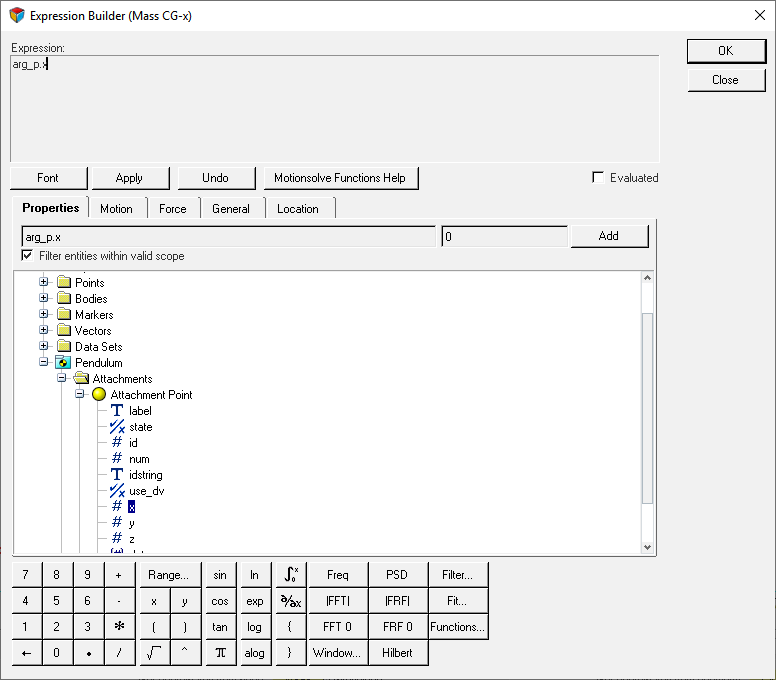
Figure 4.The expression arg_p.x will automatically fill the Expression area. -
Add +50 to the epression.
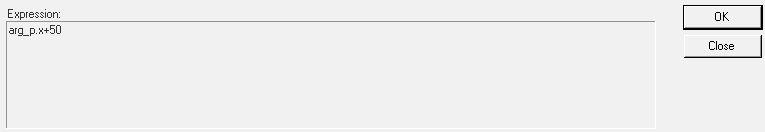
Figure 5. -
Repeat steps 5
through 10 for the
Y and Z coordinates.
-
For the Z coordinate, specify the expression as
arg_p.z+100.
Note: You can also add the Y and Z coordinate expressions by copying the X coordinate expression and editing it.
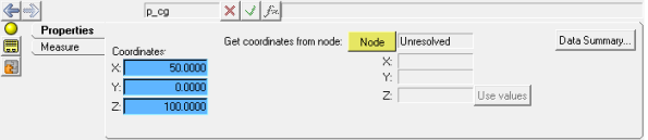
Figure 6.Note: the background color of the field changes for parametric expressions.
-
For the Z coordinate, specify the expression as
arg_p.z+100.
Add a Body to the System
In this step you will add a body to the Pendulum system.
-
Open the Add Body or BodyPair dialog in one of the
following ways:
- Right-click on Pendulum and select .
- On the Reference Entity toolbar, right-click the
 (Bodies) icon.
-
In the Properties tab, specify the Mass as 1, and the
Ixx, Iyy, and Izz Intertia properties as 1000.
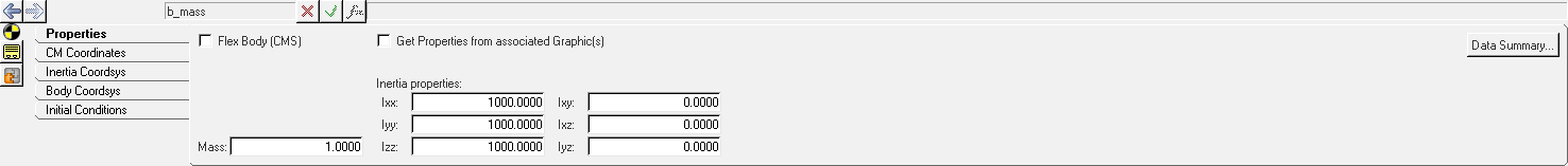
Figure 7. -
Under Origin, double-click on
 .
.
-
In the dialog, select Mass CG and click
OK.
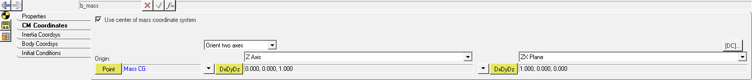
Figure 8.
Add Graphics to the System
In this step, you will add graphics to the Pendulum system.
-
Open the Add Graphic or GraphicPair dialog in one of the
following ways:
- Right-click on Pendulum and select .
- On the Reference Entity toolbar, right-click the
 (Graphics) icon.
-
In the Graphics panel, configure the Connectivity tab.
-
Under Parent, double-click the
 collector.
-
Under Origin, double-click the collector.
-
Under Direction, double-click the collector.
-
In the dialog, specify the Attachment Point and
click OK.
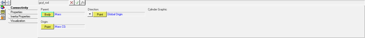
Figure 9.
-
Under Parent, double-click the
-
In the Graphics panel, under the Connectivity tab specify the Parent body as
Mass and the Origin point as Mass
CG.
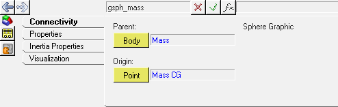
Figure 10. -
In the Properties tab, specify a Radius of 25.
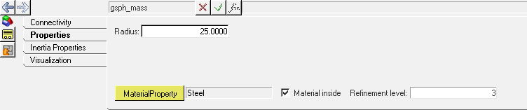
Figure 11.
Add a Joint to the System
In this step you will add a revolute joint to the Pendulum system.
-
Open the Add Joint or JointPair dialog in one of the
following ways:
- Right-click on Pendulum and select .
- On the Reference Entity toolbar, right-click the
 (Joints) icon.
-
In the Joints panel, from the Connectivity tab double-click on
 .
.
-
Double-click
 .
.
-
From the dialog, expand the folders and select Attachment Body.
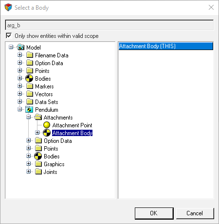
Figure 12.Tip: You can also click the Global Triad and pick Ground Body via the Attachment Body. -
Under Origin, double-click the
collector.
-
Double-click
 and select Global Y.
-
Click
 (Save model) and save the file
as pend_gui.mdl to your <working
directory>.
(Save model) and save the file
as pend_gui.mdl to your <working
directory>.
Export the System Definition
In this step you will learn how to export your system definition to your <working directory>.
-
Click the Export radio button.
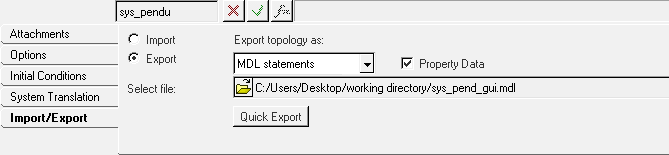
Figure 13. -
Click the
 (file browser) and browse to your
<working directory>.
(file browser) and browse to your
<working directory>.
Instantiate the System Definition
In this step you will learn how to instantiate a system definition.
-
Click the (file browser) and browse to your
<working directory>.
-
Select the sys_pend_gui.mdl file and click
Open.
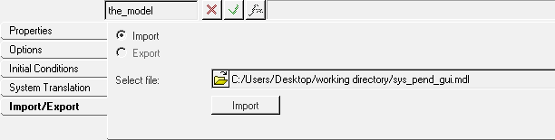
Figure 14. -
Change the Label to Pendulum 2 and the Variable to
sys_pendu_2.
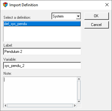
Figure 15. -
In the Attachments tab, resolve the and attachments.
-
Double-click the collector.
-
In the Model Tree, click . Then click OK.
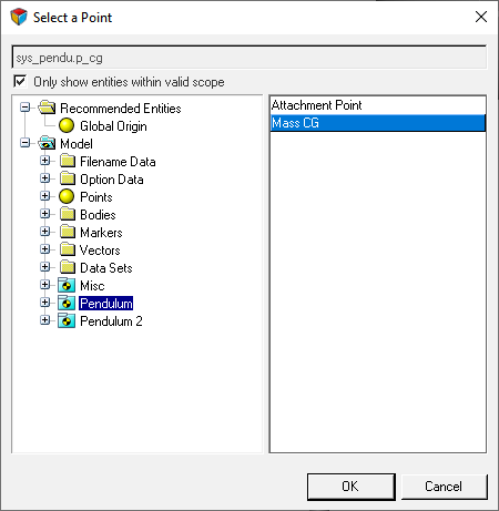
Figure 16. -
Double-click the collector.
-
Double-click the
-
Save the model to your <working directory> as
pend_2_gui.mdl.
You can reuse the same system definition to instantiate several times either within the same model or in a different model.