Turbulent Flow Over an Oscillating Rigid Body Assembly
In this application, AcuSolve is used to simulate the fluid-structure interaction of a fluid moving over a cylinder/plate assembly. AcuSolve results are compared with experimental results as described in Gomes and Lienhart (2009). The close agreement of AcuSolve results with the experimental results validates the ability of AcuSolve to model cases in which the fluid forces lead to structural motions.
Problem Description
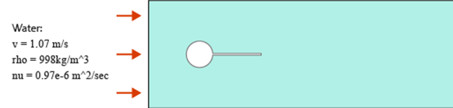
Figure 1. Critical Dimensions and Parameters used for Simulating Rigid Body Motion of Flow Past a Cylinder/Plate Assembly
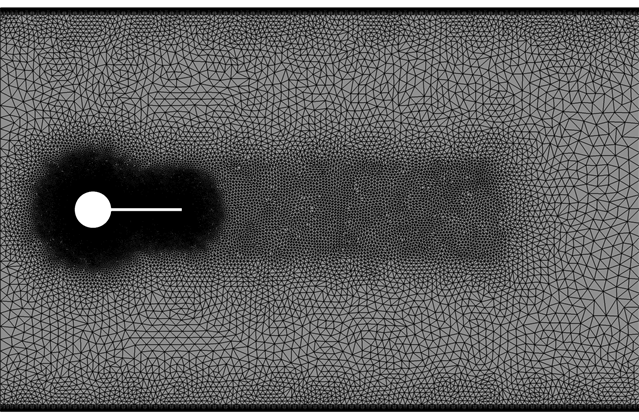
Figure 2. Mesh used for Simulating Rigid Body Motion of Flow Past a Cylinder/Plate Assembly
The simulation was performed as a two dimensional problem by constructing a volume mesh that contains a single layer of elements extruded in the cross stream direction, normal to the flow plane and by imposing symmetry boundary conditions on the extruded planes. The upper and lower walls are specified as no-slip and the inlet velocity is specified to match the conditions of the experiment (Gomes and Lienhart 2009).
AcuSolve Results
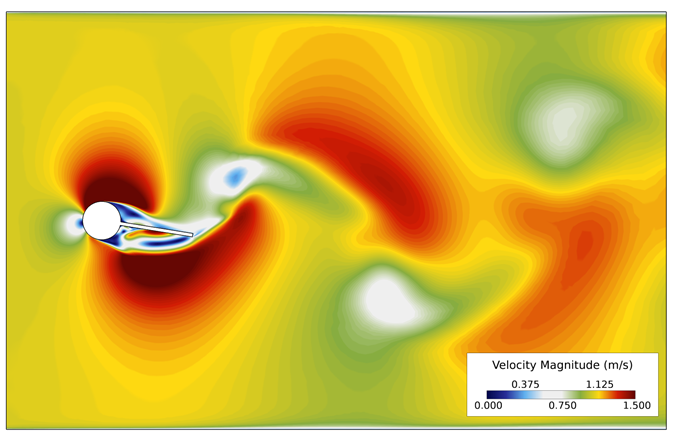
Figure 3. Velocity Contours Near the Assembly for a Single Time Step During the Simulation
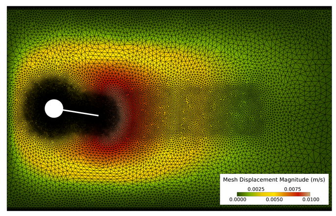
Figure 4. Mesh Displacement Contours Near the Assembly for a Single Time Step During the Simulation
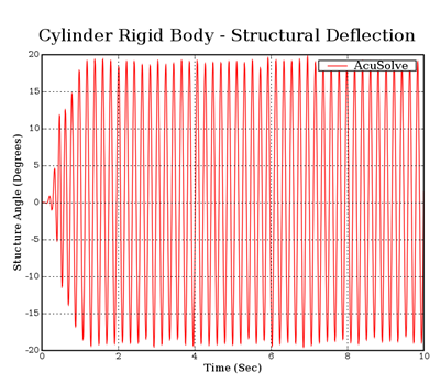
Figure 5. Rigid Body Displacement of the Assembly as a Function of Time, Showing the Oscillation Develop into the Pseudo-Steady Motion
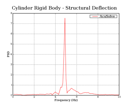
Figure 6. FFT of the Rigid Body Displacement Angle, Showing Power Spectral Density as a Function of Frequency
Summary
The AcuSolve solution compares well with experimental data for flow past an oscillating cylinder/plate assembly. In this application, water moves over the cylinder/plate assembly, giving rise to unsteady loading that causes the body to rotate as a rigid body. The good agreement with the natural frequency of oscillation compared to the experimental data demonstrates that AcuSolve is capable of predicting fluid forced motion with an internal rigid body dynamic solver.
Simulation Settings for Turbulent Flow Over an Oscillating Rigid Body Assembly
AcuConsole database file: <your working directory>\cylinder_rigidbody_turbulent\cylinder_rigidbody_turbulent.acs
Global
- Problem Description
- Analysis type - Transient
- Turbulence equation - SST
- Mesh Type- Fully Specified
- Auto Solution Strategy
- Final Time - 10.0
- Initial Time Increment- 0.005
- Convergence tolerance- 0.001
- Max stagger iterations- 3
- Material Model
- Water
- Type- Constant
- Density- 998.0 kg/m3
- Viscosity- 0.00096806 kg/m*sec
- Water
- Mesh Motion
- Interpolated
- Type- Interpolated Motion
- Interpolated motion surfaces
- Bottom
- Top
- RigidBody
- Type- Rigid Body Dynamic
- Z rotation- Active
- Mass- 0.2089 kg
- Dyadic
- X-X - 3.7 e-5 kg-m2
- Y-Y- 3.7 e-5 kg-m2
- Z-Z - 3.7 e-5 kg-m2
- Type- Rigid Body Dynamic
Model
- Interpolated
- Volumes
- Volume
- Element Set
- Material model- Water
- Mesh motion- Interpolated
- Element Set
- Volume
- Surfaces
- Body
- Simple Boundary Condition
- Type- Wall
- Mesh displacement BC type- Fixed
- Mesh motion- RigidBody
- Interpolated Motion Surface
- Simple Boundary Condition
- Bottom
- Simple Boundary Condition
- Type- Wall
- Mesh displacement BC type- Fixed
- Interpolated Motion Surface
- Simple Boundary Condition
- Inflow
- Simple Boundary Condition
- Type- Inflow
- Inflow type- Velocity
- X Velocity- 1.07 m/sec
- Turbulence input type- Auto
- Turbulence intensity type- High
- Advanced Options
- Nodal Boundary Conditions
- X-velocity
- Type- Linear
- Precedence- 2
- Curve fit variable- Y coordinate
- Curve fit values- Provided
- Y-velocity
- Type- Zero
- Z-velocity
- Type- Zero
- Simple Boundary Condition
- Bottom
- Simple Boundary Condition
- Type- Wall
- Mesh displacement BC type- Fixed
- Mesh motion- RigidBody
- Interpolated Motion Surface
- Simple Boundary Condition
- Outflow
- Simple Boundary Condition
- Type- Outflow
- Simple Boundary Condition
- Top
- Simple Boundary Condition
- Type- Wall
- Mesh displacement BC type- Fixed
- Interpolated Motion Surface
- Simple Boundary Condition
- maxZ
- Simple Boundary Condition
- Type- Slip
- Simple Boundary Condition
- minZ
- Simple Boundary Condition
- Type- Slip
- Simple Boundary Condition
- Body
References
Gomes, J. P. and Lienhart, H. (2009) Experimental Benchmark: Self-excited Fluid-structure Interaction Test Cases, in Fluid-Structure Interaction II: Modeling, Simulation, Optimization, Bungartz, H. J., Mehl, M., Schafer, M. (eds.), 383-412, Springer-Verlag.Ryhming.