Trim Elements Inside Boxes
Use the Box Trim tool trim the model, or selected subset, to fit any defined box volumes.
For example, a full car model can be trimmed along the Y=0 axis to obtain the left or right side of the car. A fixed boundary condition is applied at the trimmed edges. It also removes the FE entities outside of the box, and cleans the model so that it is a runnable deck. The axis directions and terminology are based on modeling standards in the automotive industry.
Restriction: This option is available in the LS-DYNA, Nastran, Abaqus, OptiStruct, and
Radioss profiles.
Different scenarios for using the Box Trim tool include:
The Box Trim tool is very useful when you are doing a system-level analysis, and when
portions of a full vehicle model include few complete subsystems or partial
subsystems.
Note: This tool can only be used for 1st order elements.
-
From the Elements ribbon, click the Box
Trim tool.

Figure 1. -
In the fist microdialog, click
 to add a
new box volume.
A second microdialog appears.
to add a
new box volume.
A second microdialog appears. - Optional:
Resize and relocate the box.
- Click
 to manipulate the box with the Move.
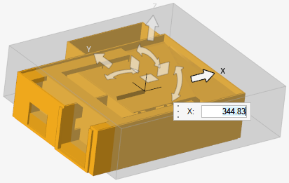
Figure 2. - Drag a face or an edge.
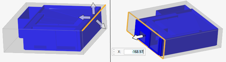
Figure 3.
- Click
-
Use the drop-down menu in the microdialog to orient the
box with the global axes or to a best fit.

Figure 4. - Optional:
Click
 on the guide bar to create
Single Point Constraints (SPCs) for all of the nodes along the trimmed edges.
You can also set options that help clean the trimmed edge elements in order to
achieve a better quality mesh.
on the guide bar to create
Single Point Constraints (SPCs) for all of the nodes along the trimmed edges.
You can also set options that help clean the trimmed edge elements in order to
achieve a better quality mesh.
Tip: Click  on the guide bar to clear all
boxes and start over.
on the guide bar to clear all
boxes and start over.