hexa (area_tie)
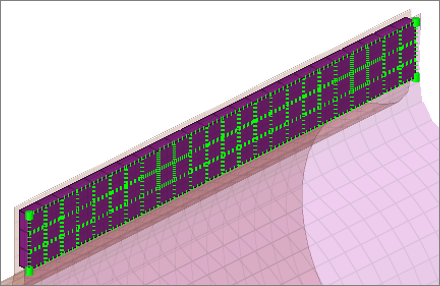
Creates hexa elements between shell and/or solid elements in order to connect them using a tie contact definition. The hexa element nodes will project and touch the shell and/or solid element faces. During the realization, a default tie contact and referencing main and secondary sets are created; unless defined differently, the hexas are assigned a default property and material, and are organized into a component with the same name base as the property.

Figure 1.
Hexa Realization Options
| Option | Action |
|---|---|
| coats | Defines the number of hexa elements required along the
thickness. Note: Multiple
solid coats are supported when adhesive-hemming is
selected.
|
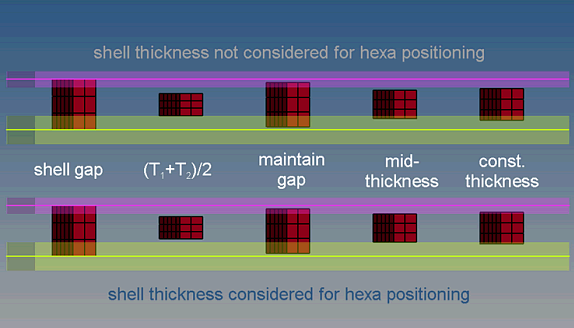
| thickness |
Select a method for defining the thickness of a hexa
weld.
Note: The exact hexa position is also influenced by
the option consider shell thickness and offset for hexa
positioning.
 Figure 2. |
| direction node | Define the direction node. |