Manage E-Line
Use Manage E-Line tool to review and manage E-lines.
- E-lines need to be created before starting this step. If E-lines are already realized in Create E-line step this step is optional.
The E-line Manage workflow is designed to facilitate rapid E-line realization and editing both for advanced users as well as part time analysts. There are three workflows in this tool:
Fast Realize
-
From Setup group, select Manage
E-Line.
 Figure 1.
 -
Click
 .
This realizes the selected E-lines. Relevant properties, local system collectors and other components will be created and listed in the model browser.Unrealized E-lines of the selected type will be realized. FE-entities representing the E-line will be created.
.
This realizes the selected E-lines. Relevant properties, local system collectors and other components will be created and listed in the model browser.Unrealized E-lines of the selected type will be realized. FE-entities representing the E-line will be created.
Manual Realize and Edit
-
Deactivate
 to open
Manual mode.
to open
Manual mode.
-
Optional: You can manually edit or update the parameters if
needed.
 Figure 2.
 -
Click
 .
Unrealized E-line(s) will be realized and, if they are edited, parameters will be updated. FE-entities representing the E-line will be created.Note: Before proceeding to next step all E-lines should be realized and the necessary parameters should be updated.
.
Unrealized E-line(s) will be realized and, if they are edited, parameters will be updated. FE-entities representing the E-line will be created.Note: Before proceeding to next step all E-lines should be realized and the necessary parameters should be updated.
Review E-Lines Table
- Get an overview of all the E-Lines in model.
- Edit and update E-Lines parameters for a single or multiple E-Lines (see Manage E-Lines Options).
- Review and update Gap and Tolerance values for Interfaces or Map Interface Names from imported DTS file.
- Map Material to Squeak E-lines.
 Figure 4.
 - Delete E-Lines.
This removes selected E-lines from model.
 - Realize E-Lines.
When you edit and update a parameter for a realized E-Lines, the line status changes to unrealized. For such changes, you will have to re-realize the updated line.
 - Renumber E-Lines.To renumber selected E-lines:
- Specify an interval.
- Click on
Note: Last four digits of ID is unable to edit and will be set and controlled automatically. Smallest E-line ID is therefore 10000.- Material Mapping
You can use the existing template materials, import a user defined material database file or connect to Ziegler PEM Material Database. Both contains data referring to pairs of material and their compatibility. These data are obtained by stick-slip testing and are used in evaluation the Squeak simulation (Squeak Evaluation ).
The idea behind mapping of materials is to incorporate information coming from the material database, without interfering with the cards of existing materials of the model in hand. You need to associate materials of parts at the interfaces you want to study to materials in the database. This is done to assign stick-slip testing results to an E-Line which is then used in post-processing of the E-Lines for Squeak evaluation.- Map Material using template values:
- Assign Main and Secondary material for each
Squeak E-line.Note: Not all material combinations have a match, some combinations have a non-existent risk of Squeak, Impulse Rate range for these are 100-100.
- Assign Main and Secondary material for each
Squeak E-line.
- Map Material using user defined Material Compatibility
Matrix:
- Load Material File using Import (unless already done).
- Assign the imported Main and Secondary material for each Squeak E-line by selecting them in table
- Map Material when Connected to Ziegler Database:
- Connect to Ziegler Database using Import (unless already done).
- In Material Mapping tab click
 .
. - Select E-line to Map Material.
- Select Type, Manufacturer and Brand for both
Main and Secondary Material.
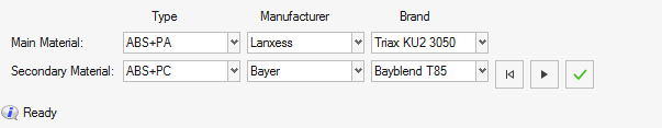 Figure 5.
 - Click to map
selected material pair to selected E-lines.
 Figure 6.
- Map Material using template values:
 - Select All
 - Unselect All
 - Reverse
Selection
- Reverse
Selection - Navigate buttons to
cycle through and isolate one interface at a time.
- Navigate buttons to
cycle through and isolate one interface at a time.
Manage E-Lines Options
- Status
- Contains the E-Lines realization status
 - Unrealized E-Lines
 - Realized E-Lines
 - Failed to realize
E-Lines
- Failed to realize
E-Lines- E-Lines ID
- A unique ID for each E-line along with the number of connections for respective E-Lines (last digits).
- Type
- Defines what type of phenomena to evaluate along the line – Rattle or Squeak.
- Interface Name
- Interface name from imported DTS file. Assign Interface to respective E-line in model to map the GD&T data.
- Gap
- Gap value for the interface in the specified gap direction. This is defined based on the Gap assignment method.
- Tolerance
- Design tolerance for gap in the specified gap direction. This is defined based on the Gap Assignment method.
- (Impulse Rate)⁻¹ range
- Inverse of Impulse Rate range is a measure of the material pair compatibility. This is defined based on the material mapping and only applies to Squeak lines.
- Contact Type
- Define Contact type for the E-line. This is based on Youngs' modulus value of the Main and Secondary FE material.
- Gap Direction
- Realization Projection direction that controls creation of the local coordinate systems which determines the Gap direction.
- Spacing
- Value for the spacing between two adjacent Evaluation Points on an E-line.
- Search Distance
- Value for search / gap tolerance between the selected Main-Secondary component.
- Main FE Material
- Assigned FE material for main component in the E-Line.
- Secondary FE Material
- Assigned FE material for secondary component in the E-Line.
- Main Material
- Mapped Material from Stick-Slip testing for main component in the E-Line.
- Secondary Material
- Mapped Material from Stick-Slip testing for secondary component in the E-Line.