HM-4650: Seat Deformer with LS-DYNA Pre-Simulation
In this tutorial, you will learn how to setup a LS-DYNA model to simulate the seat deformation under the dummy.
The driver seat and environment used in this tutorial are based on the LS-DYNA Toyota Yaris model, provided on the National Crash Analysis Center (NCAC) website.
The LS-DYNA dummy model used in this tutorial is a release version of the THOR-Mod Kit/Metric crash test dummy with SD3 shoulder posted on the NHTSA website.
Load the LS-DYNA Profile
In this step, you will load the LS-DYNA profile in HyperMesh.
- Start HyperMesh Desktop.
- In the User Profiles dialog, set the user profile to LsDyna.
- Set the template drop-down to Keyword971_R8.0.
Retrieve and View the Model File
In this step, you will open the model file and view it in HyperMesh.
-
Open a model file by completing one of the following options:
- Click from the menu bar.
- Click
 on the Standard
toolbar.
on the Standard
toolbar.
- In the Open Model dialog, open the seat_deformer.hm file.
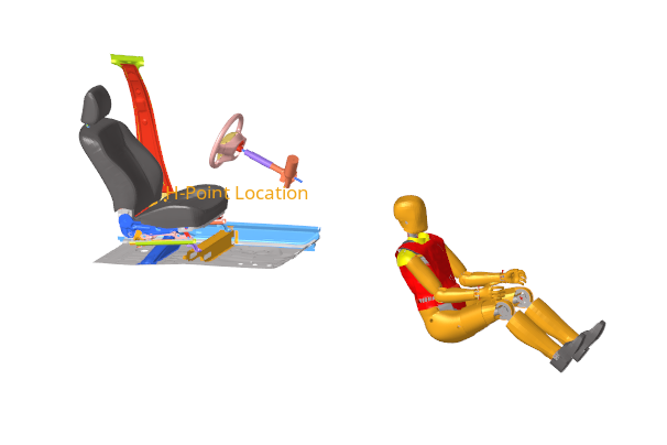
Figure 1.
Position the Dummy to its H-Point Location
In this step, you will move the dummy to its H-Point Location on the seat.
-
In the Dummy Browser, click on the
THOR_FE dummy entity.
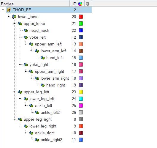
Figure 2.The global positioning parameters are activated in the Entity Editor. -
Under H-Point location, click on the coordinates area and then click
 .
.
-
In the graphics area, select the node tagged as H-Point
Location on the seat as seen in Figure 3.
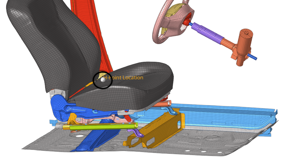
Figure 3. -
In the panel area, click
proceed.
The dummy automatically moves to the selected HPoint location as seen in Figure 4.
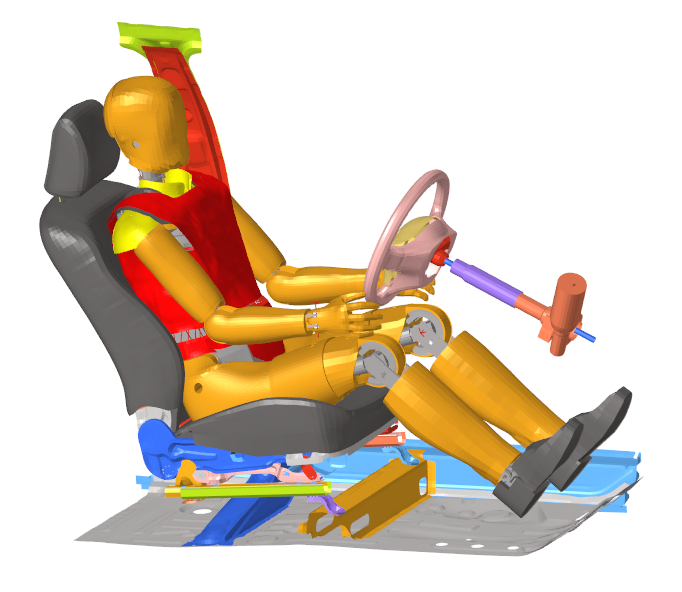
Figure 4.
Generate the Seat Deformer Model
In this step, you will generate the Seat Deformer model for the LS-DYNA simulation.
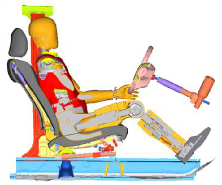
Figure 5.
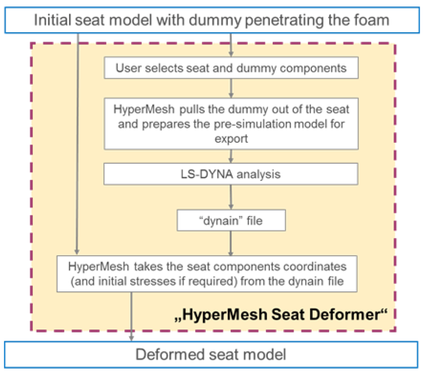
Figure 6.
- Open the Seat Deformer tool from the menu bar by clicking .
- In the PreSimulation dialog, under PreSimulation Set-Up, set Unit System to mm,ms,kg.
-
Select the dummy components penetrating the seat foam.
-
In the Select Components dialog, select the
components shown in Figure 7 and click OK.
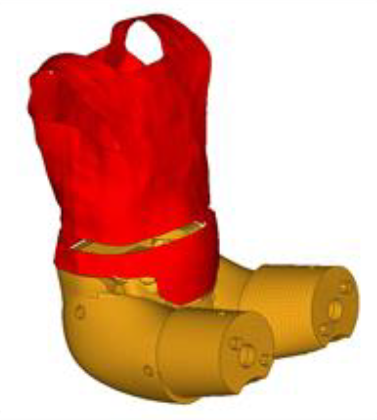
Figure 7.
-
In the Select Components dialog, select the
components shown in Figure 7 and click OK.
-
Select the seat mechanism.
-
In the Select Mechanisms dialog, select
Driver_Seat and click OK.
Note: By selecting a mechanism, only the components defined in the bodies will be taken into account. The nodes will not be taken into account. In this example, the Seat_Cushion body is composed of a set of components and a set of nodes. The nodes will not be taken into account in the process.
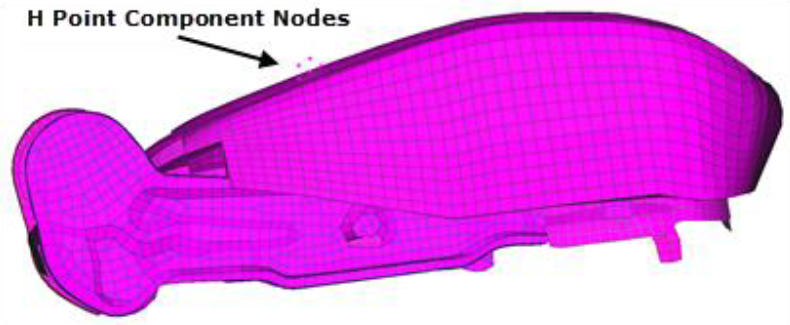
Figure 8.
-
In the Select Mechanisms dialog, select
Driver_Seat and click OK.
-
Select the fixed nodes of the seat.
-
Select the components depicted in Figure 9.
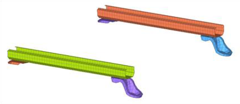
Figure 9.
-
Select the components depicted in Figure 9.
- In the Dummy Displacement Direction field, enter -0.3, 0, -0.7.
- In the Export File field, specify the file path and name of your working directory.
- In the Dummy Velocity field, enter 1.0 mm/ms.
- In the Dummy Displacement Step field, enter 20.0 mm.
- In the Imposed Contact Thickness field, enter 1.0 mm.
- Click Export to start the export process of the LS-DYNA seat deformer pre-simulation input deck.
Review Simulation Results and Update the Model
In this step, you will review the seat deformer simulation results and update the initial model in HyperMesh.
-
Review the simulation results.
-
Find the d3plot files in HyperMesh to visualize the
animations.
The displacement fields on the seat should look similar to Figure 10.
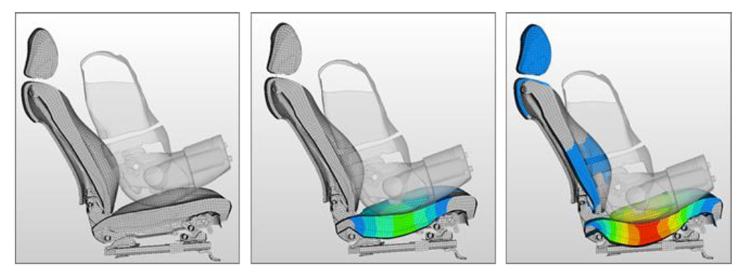
Figure 10.
-
Find the d3plot files in HyperMesh to visualize the
animations.
-
Update the initial model.
-
Select the dynain file of the seat deformer simulation.
Default updates the node coordinates of the seat and the solid elements with their corresponding initial stress card. The resulting updated model should look similar to Figure 11.
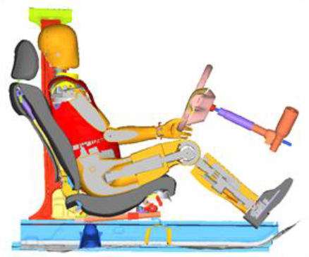
Figure 11.
-
Select the dynain file of the seat deformer simulation.