HM-4640: Dummy Positioner
In this tutorial, you will learn the different Default functionalities available to position a dummy in its environment.
The driver seat and environment used in this tutorial are based on the LS-DYNA Toyota Yaris model, provided on the National Crash Analysis Center (NCAC) website.
The LS-DYNA dummy model used in this tutorial is a release version of the THOR-Mod Kit/Metric crash test dummy with SD3 shoulder posted on the NHTSA website.
Load the LS-DYNA Profile
In this step, you will load the LS-DYNA profile in HyperMesh.
- Start HyperMesh Desktop.
- In the User Profile dialog, set the user profile to LsDyna.
- Set the template drop-down to Keyword971_R8.0.
Retrieve and View the Model File
In this step, you will open the model file and view it in HyperMesh.
-
Open a model file by completing one of the following options:
- Click from the menu bar.
- Click
 on the Standard
toolbar.
on the Standard
toolbar.
- In the Open Model dialog, open the dummy_positioner.hm file.
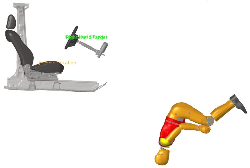
Figure 1.
Position the Dummy to its H-Point Location
In this step, you will move the dummy to its H-Point Location on the seat.
-
In the Dummy Browser, click on the
THOR_FE dummy entity to activate the global
positioning parameters in the Entity Editor.
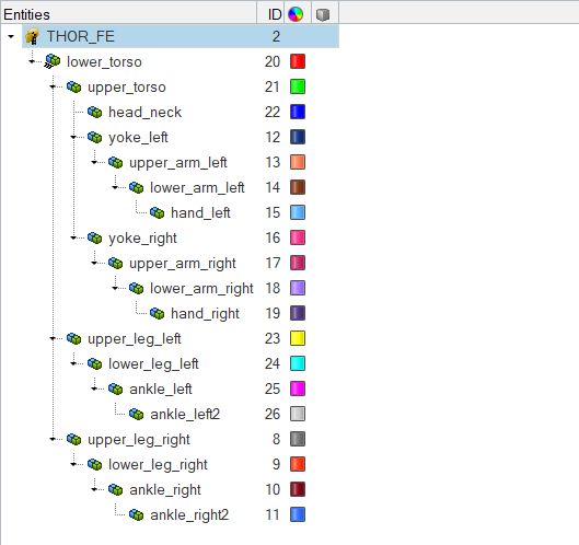
Figure 2. -
Under H-Point location, click on the coordinates area and then click
 .
.
-
In the graphics area, select the node tagged as H-Point
Location as seen in Figure 3.
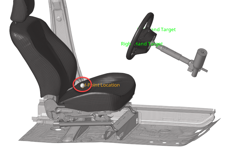
Figure 3. -
In the panel area, click proceed.
The dummy automatically moves to the selected H-Point location.
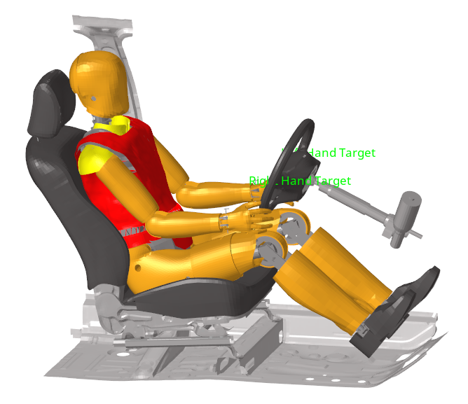
Figure 4.
Manually Position the Limbs
In this step, you will manually position the lower_leg_left and lower_leg_right body entities.
-
In the Dummy Browser, click the
lower_leg_left body entity.
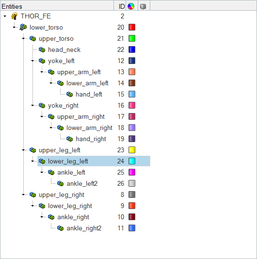
Figure 5.The joint manipulator appears in the graphic area, and the Entity Editor opens.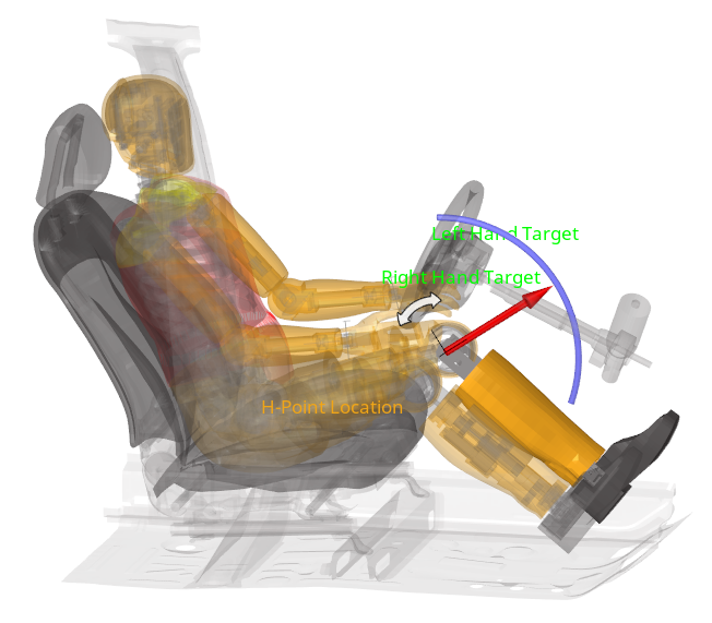
Figure 6.
Automatically Position the Hands
In this step, you will position the hands automatically .
-
Position the left hand.
-
Click .
-
In the graphics area, select the node tagged as Left Hand
Target as seen in Figure 7.
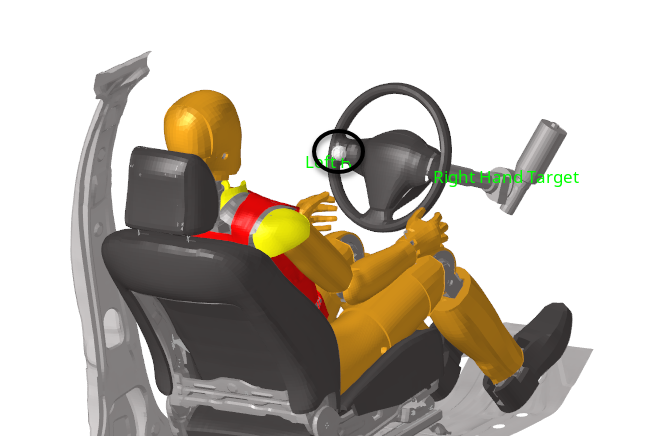
Figure 7.
-
Click
-
Position the right hand.
-
In the Select multi nodes dialog, click
 to
add a second row to define the Source Point and Target Point for the
right hand.
to
add a second row to define the Source Point and Target Point for the
right hand.
-
Click .
-
In the graphics area, select the node tagged as Right Hand
Target as seen in Figure 8.
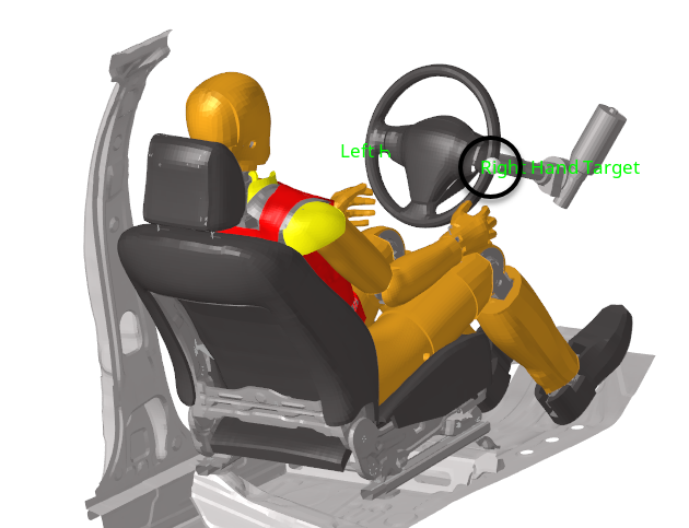
Figure 8.
-
In the Select multi nodes dialog, click
-
In the Entity Editor, click Select
Bodies.
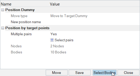
Figure 9. -
In the Entity Editor, click Move
to activate automatic limbs positioning.
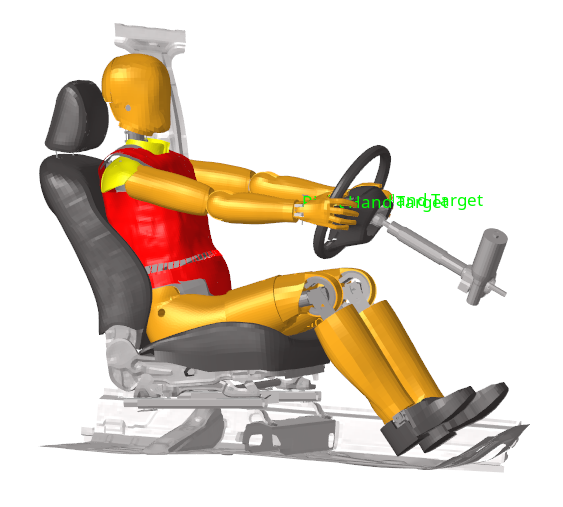
Figure 10.
Save and Retrieve Dummy Positions
In this step, you will save and retrieve dummy positions.
Link the Dummy to a Seat Mechanism
In this step, you will link the dummy to a seat mechanism.
-
In the Mechanism Browser, expand the
Driver_Seat mechanism to observe the different joints
and bodies defined.
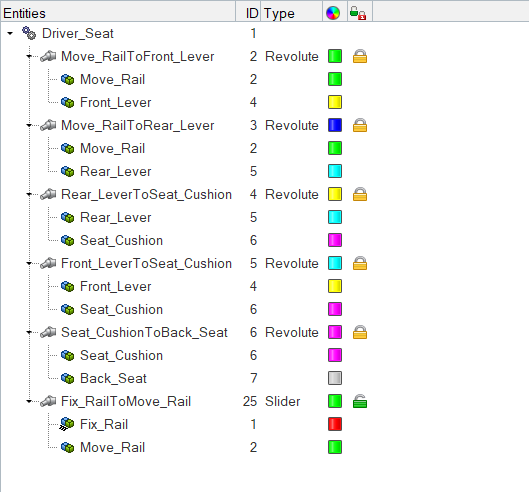
Figure 11. -
Create a constraint on the ankle_left2 body.
-
In the Entity Editor, click the
Fixed DOF field and select the first four
checkboxes and the last checkbox.
The three translations and the rotations RX and RZ of the selected body are fixed in the global coordinate system. RY is free.
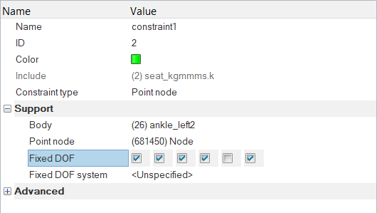
Figure 12.
-
In the Entity Editor, click the
Fixed DOF field and select the first four
checkboxes and the last checkbox.
-
In the Entity Editor, Current Distance field, enter
-50.0.
Notice how the dummy moves with the seat and how the position of the legs and feet are updated because of the constraints defined on the feet.
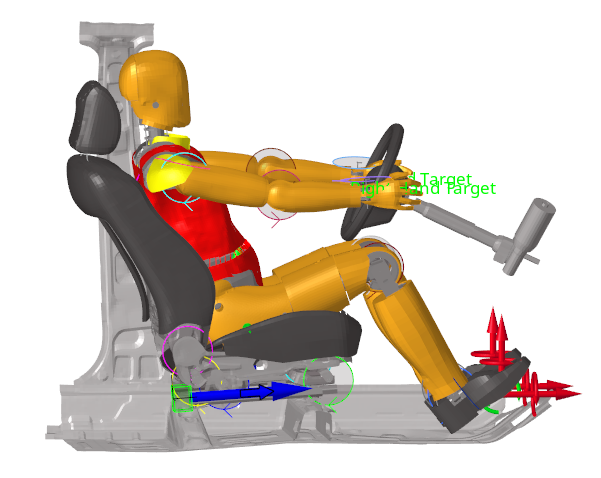
Figure 13.