In this tutorial you will create a seatbelt system and all related solver seatbelt
entities.
This tutorial uses the SEAT_MODEL_HM2020.HM file that can be found
in the <hm.zip>. Copy the file(s) from this directory to your
working directory.Figure 1.
Load the User Profile
In this step you will load the user profile.
Start HyperMesh Desktop.
In the User Profile dialog, set the profile to LS-DYNA
R11.1.
Load the Model
In this step you will load the model file.
Open a model file by completing one of the following:
Click File > Open > Model from the menu bar.
Click on the Standard toolbar.
In the Open Model dialog, open the
seat_model_hm2020.hm file.
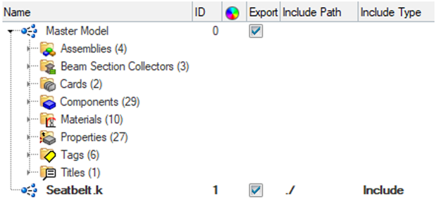
Create a Seatbelt Include File
In this step you will create a seatbelt include file.
In the Model Browser, right-click and create a new Include
file.
Rename the Include file to Seatbelt.k.
Switch to the Model Browser Include View.
Figure 2.
Create the Seatbelt Mesh
In this step you will create a seatbelt mesh.
From the Tools menu, select Seatbelt.
The Seatbelt Browser opens.
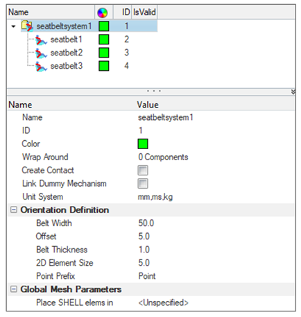
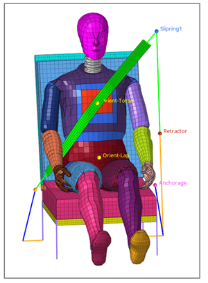
In the Seatbelt Browser, right-click and select Create > SeatbeltSystem.
A seatbelt system is generated with three seatbelt
segments.
Select the root of the SeatbeltSystem to activate the Entity Editor.
Figure 3.
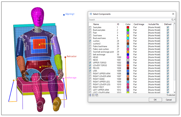
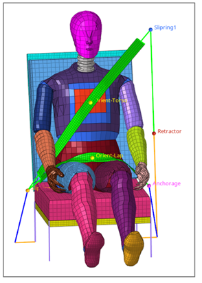
In the Entity Editor:
Select the Wrap Around Components as shown in
the following image.
Figure 4.
Activate the Create Contact option to
automatically generate the contacts between belt and wrap around
components.
Change the 2D Element Size to 10.0.
In the Seatbelt Browser, select
seatbelt1 to activate this seatbelt segment.
In the Entity Editor for seatbelt1:
Keep the mesh type of the seatbelt segment to 1D seatbelt elements
only.
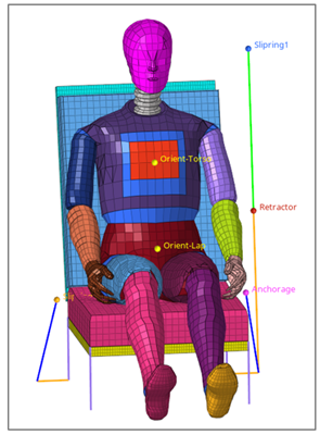
Activate the nodes selector and select the two nodes defined by the
tags "Retractor" and "Slipring1" to define the belt path of
seatbelt1.
The seatbelt1 1D mesh is automatically generated. Figure 5.
In the Seatbelt Browser, select
seatbelt2 to activate the seatbelt segment.
In the Entity Editor for seatbelt2:
Keep the mesh type of the seatbelt segment to 1D & Shell
elements.
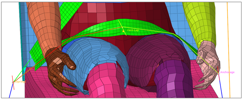
Activate the nodes selector and select the three nodes defined by the
tags "Slipring1," "Orient-Torso," and "Slipring2" to define the belt
path of seatbelt2.
The seatbelt2 mesh is automatically generated. Figure 6.
Repeat Step 8 for seatbelt3 by selecting nodes defined by "Slipring2,"
"Orient-Lap," and "Anchorage."
The seatbelt3 mesh is automatically generated. Figure 7.
Interactive Modification of the Belt Path
In this step you will modify the belt path.
In the Seatbelt Browser, select seatbelt3 then right-click
to open the context menu.
Select Interactive modification.
Select the seatbelt line path on the graphic, press and hold the left mouse
button, and move the belt line upward to modify the belt path.
Press Esc to terminate the process.
Figure 8.
Create Solver Seatbelt Entities
In this step you will create solver seatbelt entities.
In the Seatbelt Browser, select the control point named
Point1 in seatbelt1.
Right-click and select Create > Retractor.
Click the Create button at the bottom of the browser to
create an *ELEMENT_SEATBELT_RETRACTOR at this location.
Figure 9.
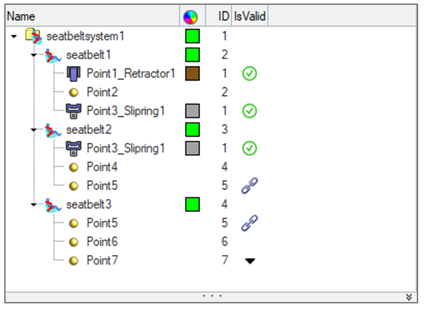
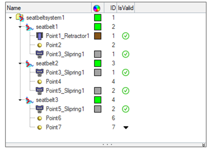
In the Seatbelt Browser, select the control point named
Point3 in seatbelt1.
Right-click and select Create > Slipring 1D.
Click the Create button at the bottom of the browser to
create an *ELEMENT_SEATBELT_SLIPRING at this location.
Figure 10.
Repeat Step 4 through Step 6 for Point5 to create another Slipring at this
location.
Figure 11.
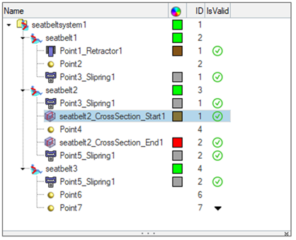
Create Solver Cross-Section on the Seatbelt
In this step you will create a solver cross-section.
In the Seatbelt Browser, select
seatbelt2.
Right-click and select Create Cross Section to open the
cross-section creation Entity Editor.
Set the Distance from Start and Distance from End to
150.0.
Click Create.
Two cross-sections are generated. Figure 12.
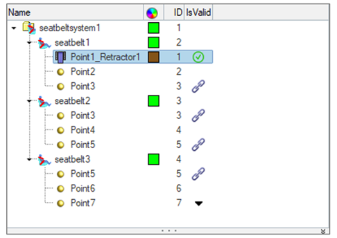
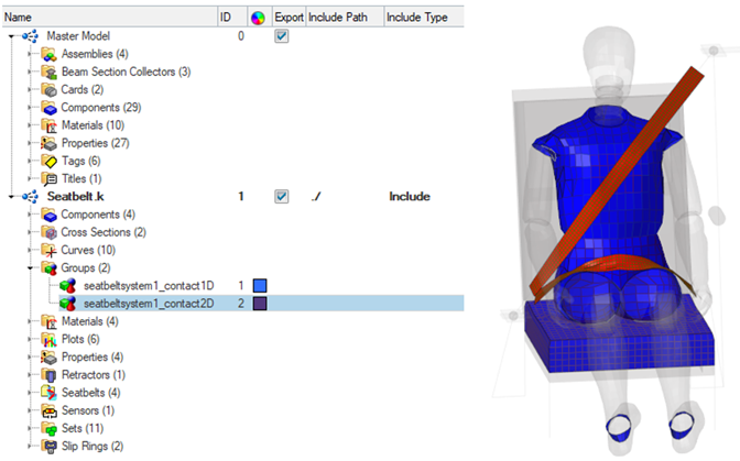
Review Entities Created in the Seatbelt Include File
In this step you will review entities created in the include file.
Open the Model Browser Include View and review the entities
created during the seatbelt creation process.
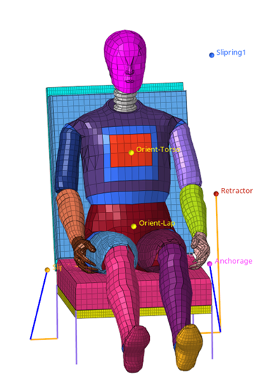 Figure 1.
  on the Standard toolbar.