CRASH-2300: Create a Seat Mechanism Using the Mechanism Browser
The goal of this tutorial is to create a seat mechanism.
- Definition of the bodies: Identified by parts and/or part sets and/or node sets. During mechanism motion, each body behaves as a rigid body.
- Definition of kinematic joints: A joint defines the relative kinematic behavior between two or three bodies. A joint defined inside the mechanism tool is independent from a joint available in the solver.
- Mechanism check: A check is available in order to verify the validity of the defined mechanism (bodies/joints).
- Move mechanism to target position: The mechanism can be automatically moved to a desired position by selecting a target node or by specifying the coordinates of the target node, for example, H-Point of a driver seat.
- Save positions: Several defined positions of a mechanism can be saved and retrieved quickly.
- Export “solver” positions: Each of the saved positions can be exported as a solver include file in which the positions of the bodies are defined via solver transformation cards.
- Export mechanism: During solver input deck export the complete mechanism, as well as the defined positions, are embedded inside the solver deck and described after the end (*END for LS-DYNA; /END for Radioss).
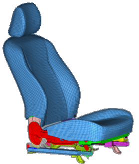
Figure 1.
Model Description
The driver seat model used in this tutorial is based on the free Toyota Yaris model, provided by the National Crash Analysis Center (NCAC).
The LS-DYNA seat model as well as the Radioss model are available. This tutorial uses the Radioss version of the seat, but each step can be reproduced using the LS-DYNA model. The files needed for this tutorial are located in example_seat_mechanism_0000.rad in the es.zip file. Copy these files into a local directory before proceeding with this tutorial.
Load the Radioss User Profile
-
From the Start menu, select or click
 on the Standard toolbar.
- Select .
- Click OK.
Load the Model File
-
Click the
 icon to browse and select the
example_seat_mechanism_0000.rad file.
icon to browse and select the
example_seat_mechanism_0000.rad file.
Open the Mechanism Browser
-
Right-click and select .
A mechanism named mechanism1 is created containing two empty bodies named body1 and body2.
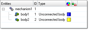
Figure 2. -
Rename mechanism1 to Driver_Seat.
- Click mechanism1 to open the Entity Editor at the bottom of the browser and type in the Name.
- Right-click in the browser.
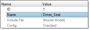
Figure 3.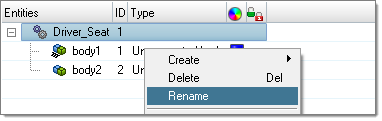
Figure 4.
Define the Bodies
For the definition of the bodies, it is necessary to know which parts or nodes belong to which kinematic assemblies. The definition of part or node sets can be done in the solver deck before starting to define the mechanism, or directly in the body Entity Editor below the Mechanism Browser. Below are the different ways you can define the content of a body inside the body Entity Editor.
-
Select a list of components.
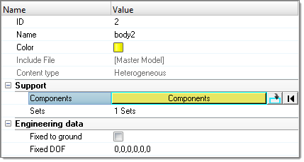
Figure 5. -
Create a set of components- Card Image GRPART (for Radioss) in set Entity Editor.
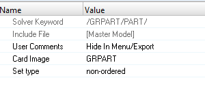
Figure 6. -
Create a set of nodes- Card Image GRNOD (for Radioss) in set Entity Editor.
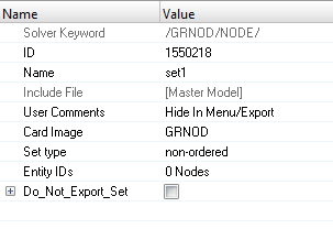
Figure 7.Note: It is recommended to use sets of parts or nodes, as these entities are directly defined and exported in the solver deck. A body can be defined by a combination of these three contents.
Create the Fix_Rail Body
-
Inside the Mechanism Browser, select
body1 to activate the Entity Editor.
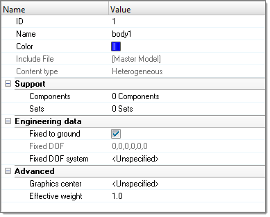
Figure 8. -
Change the name of body1 to Fix_Rail.
This body is Fixed to ground which means that all degrees of freedom of this body are locked. The
 icon attached to this body inside the Mechanism Browser
refers to this behavior.
icon attached to this body inside the Mechanism Browser
refers to this behavior. -
Inside the Entity Editor, right-click .
A dialog opens.
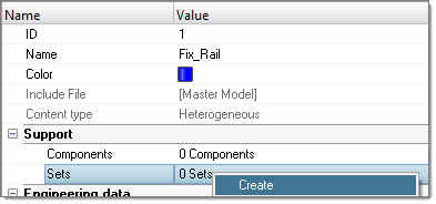
Figure 9. -
In the dialog, change the Name of the set to
Fix_Rail_Parts and change the Card Image to
GRPART.
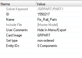
Figure 10. -
Select the components defining the Fix_Rail body by selecting them on the
display or in the Select Components dialog.
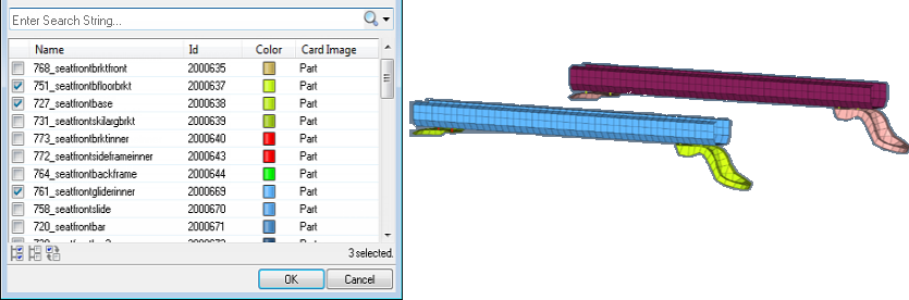
Figure 11. -
To review the body you created, right-click inside the Mechanism Browser.
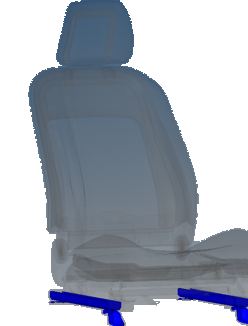
Figure 12.
Create the Move_Rail Body
-
Change the name of body2 to Move_Rail.
This body is Fixed to ground which means that all degrees of freedom of this body are locked. The
icon attached to this body inside the Mechanism Browser
refers to this behavior.
-
Click Reset Review from the context menu to turn off the body display mode.
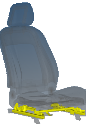
Figure 13. Move_Rail BodyNote: The 1D parts modeling the spot-weld connections between the shell meshed parts and also the set of nodes containing the master nodes of the rigid bodies have to be taken into account in this body.
Create the Other Bodies
There are five more bodies to define: Roller, Front_Lever, Rear_Lever, Seat_Cushion and Back_Seat.
-
To define the content of each body, click Sets inside
the body Entity Editor and retrieve the corresponding
sets in the model set-list, for example Front_Lever_Parts and Front_Lever_Nodes
sets for the Front_Lever body.
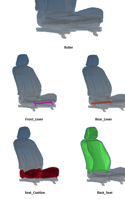
Figure 14.
Create the Joints
- Ball: Joint having the three translational degrees of freedom (DOF) blocked. This joint is defined by the center coordinates or by a node.
- Cylinder: Joint allowing a translation and a rotation around the same axis. This joint is defined by the axis (Origin+direction given by coordinates or node selection).
- Revolute: Same as Cylinder joint, without translation.
- Slider: Same as Cylinder, without rotation.
- Double Slider: A slider with a third body for which the motion is linked to
the two main bodies via scale factors:
- Motion_body3 = Factor1*Motion_body1 + Factor2*Motion_body2
- Where: 0<Factor1<1 and 0<Factor1<1 and Factor2=1-Factor1
Create the Double Slider joint
-
- In the Mechanism Browser, select
Fix_Rail and Move_Rail,
and then right-click and select Connect.
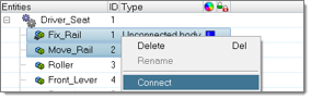
Figure 15. - Select Fix_Rail and then right-click and select
Connect To. A dialog opens listing the available
bodies. Select Move_Rail and close the dialog.
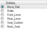
Figure 16.
- In the Mechanism Browser, select
Fix_Rail and Move_Rail,
and then right-click and select Connect.
-
Inside the joint Entity Editor select the Joint type
DoubleSlider.
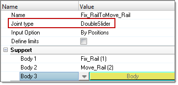
Figure 17. -
Specify Body3 by selecting Roller inside the body
list.
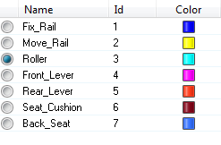
Figure 18. -
Click Origin, select a node on the rail part and click
proceed.
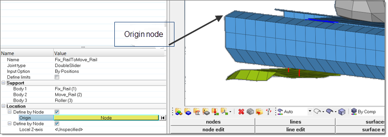
Figure 19. -
Click Origin, select a node on the rail part and click
proceed.
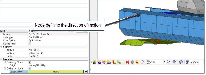
Figure 20. -
Click Create to confirm the joint.
The Double Slider joint is created in the Mechanism Browser with the three bodies defined inside, as well as on the display.
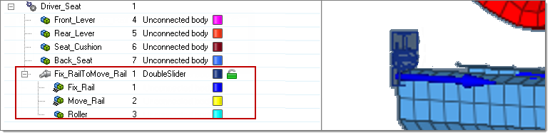
Figure 21.Note: The scale factors (Factor 1 and Factor 2) defining the relative motion between Roller and Fix_Rail and Roller and Move_Rail are set up per default to 0.5. -
In order to change these values, select the DoubleSlider
joint in the Mechanism Browser and update the value of
Factor 1 in the Entity Editor (Factor 2 is directly
computed as 1-Factor 1).
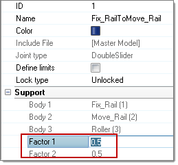
Figure 22.Define the joint limits
-
Click Create to confirm the creation of the revolute
joint.
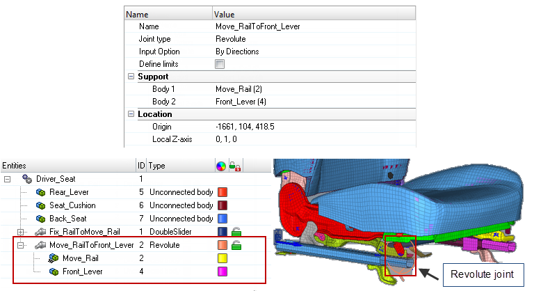
Figure 23. -
Repeat these steps to create the other revolute joints, defined as
follows:
-
Local Z-axis: 0; 1; 0: 0; 1; 0: 0; 1; 0: 0; 1; 0
The complete seat mechanism should look like the image below.
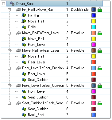
Figure 24.
-
Local Z-axis: 0; 1; 0: 0; 1; 0: 0; 1; 0: 0; 1; 0
Check a Mechanism
In order to work correctly, there are basic checks on the mechanism that need to be performed to ensure the validity of the mechanism.
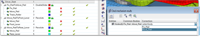
Figure 25.
Move a Mechanism
Before moving a mechanism, it is possible to specify what the joints are that are able to move and those that are locked.
Define joint lock level
-
Click the lock
 icon of a
joint.
The green icon means that the joint is locked and can move. The yellow icon
icon of a
joint.
The green icon means that the joint is locked and can move. The yellow icon means
that the joint is locked and cannot move.
means
that the joint is locked and cannot move.Move a single joint
-
Select the joint in the Mechanism Browser, for example
DoubleSlider on the actual Driver_Seat, right-click and select
Move.
You are now able to move interactively the DoubleSlider joint by activating the arrow on the display.
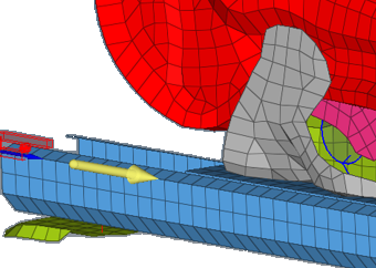
Figure 26. -
To move a joint, it is possible to use the entries in the Entity Editor. Select the
DoubleSlider, right-click and select
Move. Current distance of the joint can be modified
by giving a desired value or using the up and down arrow buttons. Moreover, you
have control on the increments of the operations by changing the Increment
value.
Move mechanism to target
Instead of moving the joints, there is the option to move the mechanism automatically by selecting a node of a body and the target position. Typically, you can select the seat H-Point. In this example, the following node represents the H-Point and belongs to the Seat_Cushion body.

Figure 27. -
To move the H-Point to a target location, select
Driver_Seat in the Mechanism Browser, right-click and select .
This opens Move to target in the Entity Editor.
- New position name: Define the name of the final position of the seat, for example Target_1.
- Multiple pairs: Yes or No – Defines if the final position is based on one node and one target (Multiple pairs = No) or based on multiple nodes and corresponding targets (Multiple pairs = Yes). For this example, select No.
- Node/Constraint: Select the seat node, which needs to be moved to the
target. Select H-Point Node.

Figure 28. - Target X,Y,Z/Node: Provide the target coordinates or pick a node (blue arrow) as the target. In this example, give the following coordinates: -1800; 330; 625.
-
Click Move, and observe that the seat is automatically
positioned matching the new H-Point target.
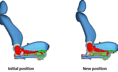
Figure 29.
Save and Retrieve Positions
A mechanism position can be saved directly in the Move to Target Entity Editor after mechanism positioning. Otherwise, after modifying manually the joint positions the final position can be saved.
-
After creating several positions you can quickly retrieve them by clicking .
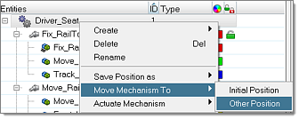
Figure 30. -
Select the desired position in the list.
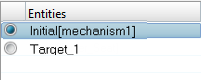
Figure 31.Note: The Initial position of the mechanism is automatically created when the mechanism has been defined for the first time, and thus, it is always possible to bring it to this initial position at any time.
Export a Position as a Solver Include File
The Mechanism Browser allows you to export any saved mechanism position to a solver file containing transformation cards and related sets of parts or sets of nodes. This allows you to position, for example a seat, using solver entities.
Export a Mechanism Using the Solver Deck
-
Click the icon to browse and select the seat_positioned_0000.rad
file.
-
Open the exported deck in a text editor and pay attention to the /END. The
created mechanism is stored between the keywords /MECHANISM_START and
/MECHANISM_END.
- /ASSEMBLY: Defines a body with the different set IDs or PART IDs, for example part set number and related set ID, number of parts and related part IDs, number of nodes set and related set ID).
/ASSEMBLY/1
Example_of_body

Figure 32.- /CONNECTION_***: Defines the type of joint between ASSEMBLY (/CONNECTION_HINGE; /CONNECTION_LINE…)
- /POSITION: Defines a position of the mechanism
Note: Reference and Initial positions should never be deleted.If you were using the LS-DYNA solver you would see *ASSEMBLY, *CONNECTION, *POSITION*ASSEMBLY
1Example_of_body

Figure 33.