HM-3220: Create a Hexahedral Mesh
Solids are geometric entities that define a three-dimensional volume. The use of solid geometry is helpful when dividing a part into multiple volumes. For example, divide a part into simple, mappable regions to hex mesh the part. Use the Solid Map panel to create a mesh of solid elements in a solid geometric volume.
In this tutorial, you will learn how to create a hexahedral mesh using the Solid map function by one volume and multisolid method.
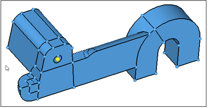
Figure 1.
Open the Model File
In this step you will open the model file, solid_map.hm.
- Start HyperMesh Desktop.
- From the menu bar, click .
- In the Open Model dialog, open the solid_map.hm model file.
Mesh the Sphere Region
In this step you will mesh the 1/8th sphere-shaped region.
-
Shade the model's geometry and surface edges by clicking
 on
the Visualization toolbar.
on
the Visualization toolbar.
-
Select the small cube-shaped solid as indicated in the following image.
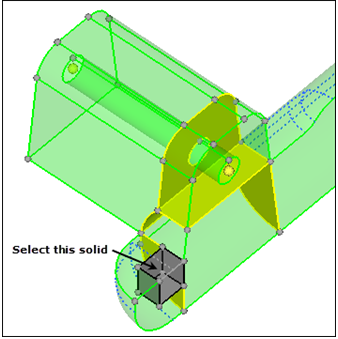
Figure 2. -
Shade the model's elements and mesh lines by clicking
 on the Visualization toolbar.
-
Select the solid as indicated in the following image.
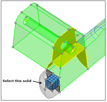
Figure 3.
Create a Shell Mesh Using Automesh
In this step you will create a shell mesh with the Automesh panel to control a mesh pattern.
-
Select the surface as indicated in the following image.
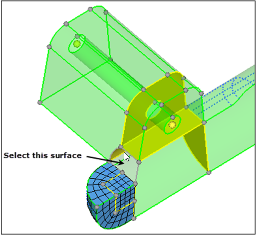
Figure 4.
Mesh the Solid Volume
In this step you will mesh the solid volume on which the surface mesh was created in Step 3.
-
Select the volume shown in the following image.
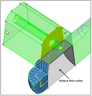
Figure 5. -
Rotate the part and note how the mesh pattern created with the Automesh panel
has been used for the solid elements.
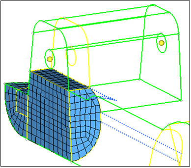
Figure 6.
Mesh Solid Volumes That Remain
In this step you will mesh the remaining solid volumes.
Save Your Work
In this optional step you will save your work.
Automated Solid Map Meshing
The capability to automate the solid map meshing process is now available.
Using the “Mappable” visualization mode in conjunction with the multi-solids feature will inform you that the solid(s) are ready for solid meshing. Using the multi-solids feature will allow for all solids within the model to be meshed in one step, provided that they are mappable.
In this section of the tutorial, you will delete all of the elements from the previous section. You will then use the Mappable visualization mode with multi-solids to solid mesh the part.
Delete Elements
In this step you will delete the elements within the model.
- Open the Delete panel by pressing F2.
- Click elems >> all.
- Click delete entity.
- Return to the main menu by clicking return.
Use the Mappable Visualization Mode
In this step you will use the mappable visualization mode.
-
Shade the model's geometry and surface edges by clicking on
the Visualization toolbar.
-
From the Geometry Visualization list, select
 .
HyperMesh color codes each solid to represent its mappable state.Note: The goal is to ensure that each solid is either 1-directional or 3-directional mappable.
.
HyperMesh color codes each solid to represent its mappable state.Note: The goal is to ensure that each solid is either 1-directional or 3-directional mappable. - Optional:
Under By mappable display mode (solids), click the color swatches to adjust the
display color of the following:
- 1dir.map: Visualization for solids that can be mapped for 3D meshing in one direction.
- 3dir.map: Visualization for solids that can be mapped for 3D meshing in three directions.
- Ignored map: Default visualization for solids that require partitioning to become mappable.
- Not mappable: Visualization for solids that have been edited but still require further partitioning to create mappable solids.
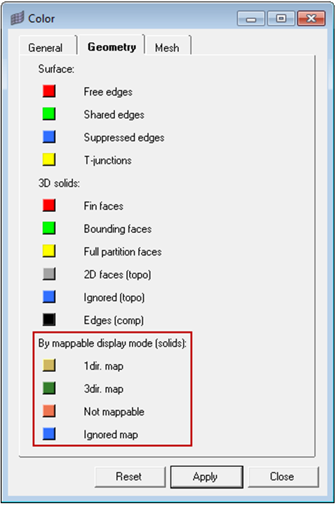
Figure 7.Note: Once in the mappable visualization mode, it is clear that there is one 3-directional mappable solid and the rest are 1-directional mappable.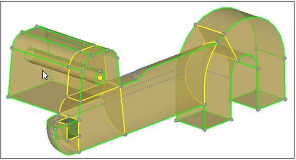
Figure 8.
Use Multi-Solid to Mesh Part
In this step you will use the multi-solid feature to mesh the part.
-
Inspect the model and note that the mesh within the solids is correctly
equivalenced.
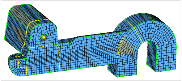
Figure 9.
Sav Your Work
In this optional step you will save your work.