HM-3130: QI Mesh Creation
HyperMesh has a set of features designed to help you achieve good element quality more efficiently.
These features use settings from the Qualityindex panel to generate or modify a mesh. This allows HyperMesh to give results that account for your preferences for which element quality checks are more or less important than others. The quality index (Q.I.) optimization features are found in the Automesh, Smooth, and Qualityindex panels. You can use these functions separately or in unison.
In this tutorial you will learn how to create and optimize a 2D mesh based on user-defined quality criteria.
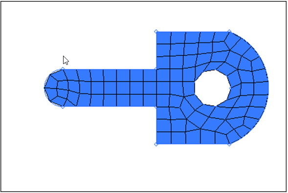
Figure 1.
Open the Model File
In this step you will open the model file, planar.hm.
- Start HyperMesh Desktop.
- From the menu bar, click .
- In the Open Model dialog, open the planar.hm model file.
- Observe the model using the different visual options available, such as rotation and zooming.
Work with Node and Element Optimization
In this step you will work with node and element quality optimization.
Within the qualityindex panel, there are tools you can use to select individual nodes or elements, and then alter the position or shape of the node/element to optimize the element quality for the surrounding elements. The element qualities are optimized according to the settings in the qualityindex panel. These features are very useful for improving element qualities in local areas of the mesh.
-
On the right-hand side of the panel, note the value for comp. Q.I.=. It should
read 85.09.
Note: Keep this number in mind so that you can judge how much progress you make in improving the element quality.
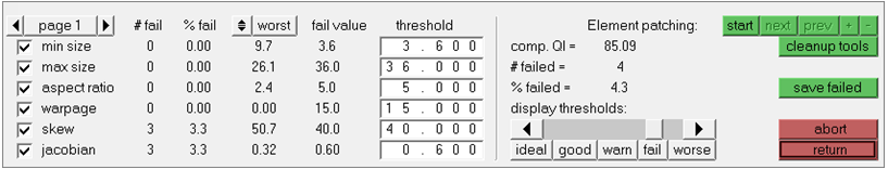
Figure 2. -
Click cleanup tools.
The QI criteria is replaced by a series of yellow buttons, each representing a tool for element cleanup.
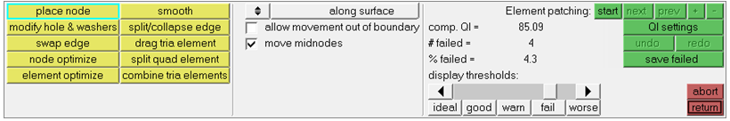
Figure 3. -
Experiment with the modify hole and washers tool. Use these options on the hole
in the mesh to reposition nodes on the hole's edges, change the radius of the
holes, and link holes with their washers so that the washers rotate or resize
along with changes made to the holes.
Option Description radial Use this option to alter the radius of a hole (and, optionally, the washer). To alter the radius of the hole, click and drag a node in the graphics area. The element orientation remains constant, but the hole may become larger or smaller based on the input. There are additional controls to enable or disable automatic remeshing when altering the hole dimensions.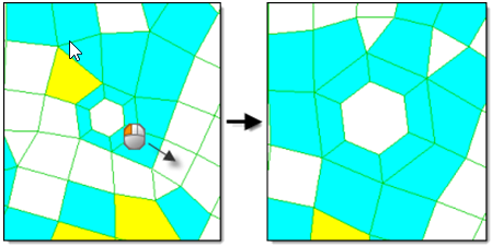
Figure 4.radius: (and edit check box) This field displays the current radius of the hole that the selected node belongs to. By default it is a display-only field. If you do not want to click and drag a node in the graphics area, you can select the edit checkbox and specify a desired radius. Once you click a node in the desired hole, the radius will change to the specified value.
angular Use this option to move the nodes around the edges of the hole without changing the hole diameter or the spacing between nodes. 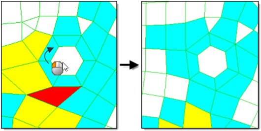
Figure 5.angle: (and edit check box) This field displays the current angle of the hole that the selected node belongs to, relative to its original (unmodified) starting position. By default it is a a display-only field. If you do not want to click and drag a node in the graphics area, you can select the edit checkbox and specify a desired angle. Once you click a node in the desired hole, the angle will change to the specified value.
radial & angular Use this option to simultaneously change the hole's radius and the orientation of nodes around its edge. Like the angular option, the node spacing remains proportionally consistent, though actual spacing will be scaled in accordance with changes in the hole radius. 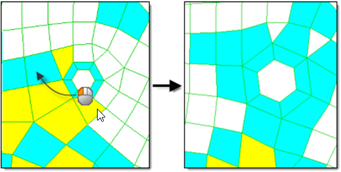
Figure 6.radial and angular: (and edit check boxes) These fields display the current angle and radius of the hole that the selected node belongs to. By default they are both a display-only field. If you do not want to click and drag a node in the graphics area, you can select both edit checkboxes and specify a desired angle and radius. Once you click a node in the desired hole, the angle and radius will simultaneously change to the specified values.
circumferential Used primarily on openings like slots, this option rotates the nodes along the circumference of the slot without altering the hole's size or shape/orientation. The capability works on enclosed slots or holes, it is not designed to work on slots with an opening. 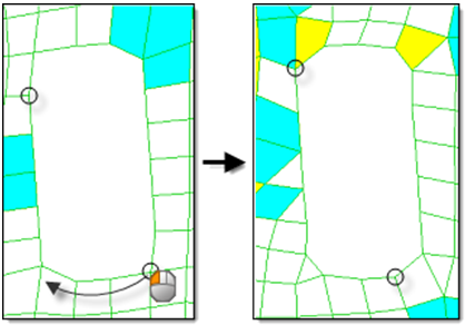
Figure 7.circumferential (and edit check box) This field displays the current arc length of the hole that the selected node belongs to. By default it is a display-only field. If you do not want to click and drag a node in the graphics area, you can select the edit checkbox and specify a desired arc length. Once you click a node in the desired hole, the arc length will change to the specified value.
link washers To change the radial or angular position of nodes, as well as drag and scale the washer nodes along with them, select this check box. In order for the link washers option to work, you must select the allow to move fixed and shared nodes check box in page 3 of the quality index panel. 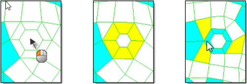
Figure 8.remesh number of layers: To specify the number of washer layers to automatically remesh after you alter the node position, select this check box. -
Experiment with the place node tool. Use the following place node options to
reposition some of the nodes in the mesh and change the shape of the surrounding
elements. To reposition a node in the mesh, click and drag it.
Note: The affected elements will change color as you reposition the node to indicate their quality grade at the node's current position. Observe how the comp. Q.I. changes.
Option Description along surface/normal to surface Use this toggle to determine which direction the node will move. To move the node along the plane or curvature of the surface, select along surface. To move the node directly away from the surface in a normal direction, select normal to surface. 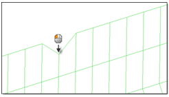
Figure 9.Note that the node cannot normally exceed the edge of the mesh.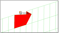
Figure 10.With the place node tool highlighted, click-and-drag a node in the graphics area to relocate it. The elements that depend on that node will dynamically adjust as you drag, resulting in a QI change.
allow movement out of boundary To move the nodes past the edges of a mesh boundary, select this check box. This option is only available when along surface is selected. 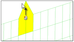
Figure 11.move midnodes To move the midnodes associated with the node you are moving, select this check box. This option is useful when you are working with second order elements. -
Experiment with the swap edge tool. Use the Swap Edge tool to consider the
elements to which the edge belongs, and find alternative orientations for
it.
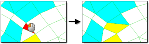
Figure 12.Each time you click an edge in the graphics area, it switches to the next valid configuration. If an edge swap will not improve element quality, a message to that effect displays in the status bar. To force the swap anyways, click the edge a second time. Additional clicks will cycle through the possible edge positions. The number of possible edge positions depends on the types of elements involved.
For a pair of trias, there are two possible positions for their shared edge. For a pair of quads, there are three possible positions. For a quad and a tria, there are six possible positions.
Reset the Part by Remeshing
In this step you will reset the part by remeshing.
You will use the AutoMesh panel to regenerate the original mesh so you can try to fix the element quality using a different method.
-
Switch the connectivity option from keep connectivity to previous
settings.
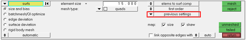
Figure 13.
Use QI Optimization Smoothing
In this step you will use QI optimization smoothing.
The Smooth panel also has quality index optimization features. In this step, you will use these features to adjust the element quality according to the settings in the qualityindex panel for an entire group of selected elements. Once you have adjusted the element quality, you will compare the smooth function to the node and element optimization used in the step 2.
Use QI Settings
In this step you will use QI settings in the Mesh panel.
The AutoMesh panel is capable of using the quality index settings to automatically decide what pattern of mesh it should generate.