HM-3270: Use the Tetramesh Process Manager
The Process Manager contains a step-by-step checklist of procedures that allow you to quickly organize and tetramesh a geometric model. Each step is formatted in a hierarchical list that provides the order in which the process must be performed. Specialized tools are also provided at each step to simplify the process. You can perform these steps manually, but it is generally faster to perform them in the Tetramesh Process Manager.
- Import geometry or a HyperMesh file
- Clean up geometry
- Organize the model (holes and features)
- Establish mesh size and pattern for the organized geometry
- Create a 2D mesh
- Clean up the 2D mesh
- Create a 3D TetraMesh
This exercise uses the tetmesh_pm.hm file, which can be found in the hm.zip file. Copy the file from this directory to your working directory.
Initiate the Process Manager
In this step you will initiate the process manager.
Import Geometry
In this step you will import geometry.
At this point, the TetraMesh Process Manger automatically assembles the TetraMesh process flow. The first step, Geometry Import, is highlighted in the tab area, and the panel area has been configured with specific panels for aiding the TetraMesh Process Manager template.
If you need to access standard HyperMesh panels, undock
the Process Manager panels to a separate dialog by clicking ![]() in the panel area. To re-dock the Process Manager panels, click
in the panel area. To re-dock the Process Manager panels, click ![]() in the Process Manager dialog.
in the Process Manager dialog.
Clean Up the Geometry
In this step you will clean up the geometry.
-
On the Visualization toolbar, select
 from the list of geometry color modes and click
 to shade the model's geometry and surface
edges.
to shade the model's geometry and surface
edges.
-
Click Isolate.
HyperMesh isolates the surfaces with free edges on them.
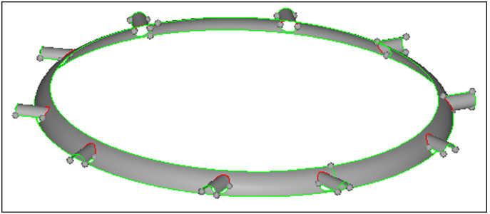
Figure 1.
Organize and Clean Up Holes
In the Organize and Cleanup Holes step, you will organize the surfaces that form holes in the model.
The TetraMesh Process Manager can automatically sort and organize holes into separate component collectors based upon their diameter. This will allow you to specify a mesh type, circumference element count, and longitudinal element size for different hole groups.
-
In the Hole Parameters Table, D< column, type 5 in
the first row and 10 in the second row.
Note: This will organize the holes into two collectors that will include holes ranging from 0 - 5 units and 5 - 10 units collectively.
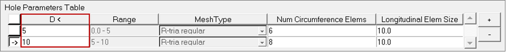
Figure 2. -
From the Model Browser, expand the
Components folder.
Note: Two new component collectors, with the name solidholes followed by the numerical average of the diameter range of the holes, are created.
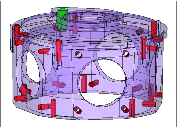
Figure 3.
Mesh Holes
In this step you will mesh holes.
Organize Features
In this step you will organize and clean up features.
In the Organize and Cleanup Features step, you will highlight and organize features that require specific mesh controls beyond the overall mesh pattern that will be applied to the remainder of the part in a later step. You will use the organizational tool to place the required surfaces into their own collector or collectors, and set a mesh size and pattern requirements for each.
-
In the panel area, click
 .
.
-
Select all five of the flat faces around the circumference of the part as
indicated in the following image.
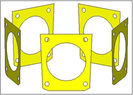
Figure 4. -
Click .
-
Select the five surfaces that are shaded gray as indicated in the following
image.
Note: You only need to select one of the two surfaces that make up a cylinder; when you click proceed HyperMesh automatically selects the other surfaces.
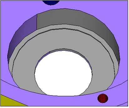
Figure 5. -
Click return.
Note: Your model should look similar to the following image, with the faces in one collector and the top hole in another. Your colors may vary slightly.
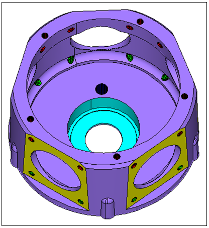
Figure 6.
Organize Fillets
In this step you will organize and clean up fillets.
Often a better mesh can be achieved if your fillets are split down the center. In the Organize and Cleanup Fillets step, you will split your fillets based on a minimum and maximum radius criteria.
Mesh Features
In this step you will mesh features.
In the Mesh Features step, you will mesh the features that you organized in step 6. The panel area will contain a table with your organized features. In the table, you will be able to select a mesh type and specify an element size for each feature.
-
Click Mesh All.
Note: Notice the distinctive Union Jack mesh pattern (
 ) in the top hole area and the connectivity of
the mesh to the previously meshed holes.
) in the top hole area and the connectivity of
the mesh to the previously meshed holes.
Organize and Clean Up
In this step you will organize and clean up the remaining portion of the model.
As the remaining surfaces are already in the component you wish them to be in, there is no need for further organization.
Mesh and Remesh
In this step you will globally mesh the remaining model.
You can select a mesh type and specify an element size for all components that remain unmeshed.
- In the panel area, type 1 in the Element Size field.
- Set Mesh Type to trias.
- Click Mesh.
- Click ACCEPT.
Clean Up Elements
In this step you will clean up elements.
At this point the model should be entirely surface meshed. Proper adherence to the previous steps ensures a surface mesh that is properly connected and controlled by the previously entered values. In the Element Cleanup step, you will verify a proper mesh and clean up any issues that are found.
Tetra Mesh Model
In this step you will tetra mesh the model.
Tetra Meshing is the final step in the TetraMesh Process Manager Template. During this step, the model will be Tetra meshed. The Process Manager automatically opens the TetraMesh panel and pre-selects all of the float and fixed elements.
-
Open the Mask panel by clicking
 on
the Display toolbar.
on
the Display toolbar.
-
Click mask.
Note: Your tetra mesh should look similar to the following image.
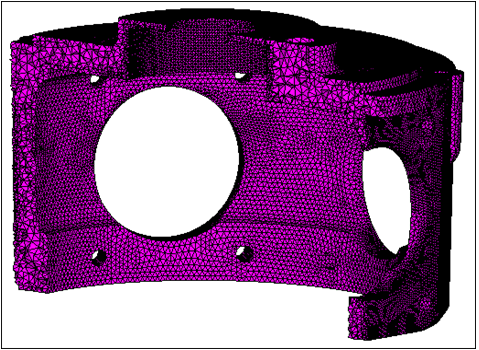
Figure 7.
Save Your Work
In this optional step you will save your work.