Define an S-parameter configuration and add it to the model.
Add an S-parameter configuration using one of the following workflows:
On the Request tab, in the
Configurations group, click the Multiport S-parameter icon.
In the configuration list, click the . From the right-click context menu, select Multiport
S-parameter.
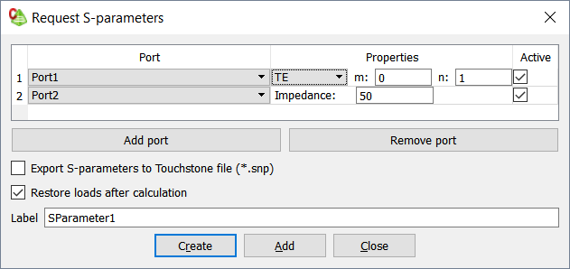
Figure 1. The Request S-parameters dialog.
In the Port column, from the drop-down list, select the port.
In the Properties column, specify the following:
For waveguide ports, specify the type (TE1 / TM2/ TEM3), indices and rotation of the
mode.
For ports other than waveguide and FEM modal ports, specify the reference impedance. If no impedance is
specified, a default reference impedance of 50 Ohm is used.
In the Active column, select the check box to use the
port as a “source” (else the port is only a “receiving” port).
Note: For example, if a Port1 and Port2 is
defined, but only Port1 is active, only S11
and S21 are calculated.
[Optional] Select the Export S-parameters to Touchstone
file check box to export the S-parameters to a .snp
file.
For each S-parameter configuration, a separate Touchstone file is created.
The file name is in the form
<FEKO_base_filename>_<requestname>(k).snp where:
FEKO_base_filename
file name of the model
requestname
request name
n
number of ports
k
a counter (integer) to distinguish between the results of
multiple requests with the same name and the same number of
ports.
Note:
Feko does not normalise the S-parameter
values to a global reference impedance when exporting S-parameters to
Touchstone file. The values are referenced to the impedance specified on
each port.
CAUTION:
Some industry tools that use the Touchstone format, often
assume that all values are referenced to a common impedance. When exporting
S-parameters for use in an industry tool that supports only a single
reference impedance, specify the reference impedance for each port to ensure
the correct interpretation.
During the calculation of S-parameters, the specified reference impedances
are added as loads to the ports. These loads remain in place after the S-parameter
calculation. If the loads are removed once the S-parameter calculation is complete,
the full matrix computation and LU decomposition step are repeated for the MoM
solution method. This is typically the most time-consuming step in the
analysis.
[Optional] Select the Restore loads after calculation
check box to remove the loads once the S-parameter calculation is
complete.
In the Label field, add a unique label for the
request.
Click Create to request the S-parameter results
and to close the dialog.
The port numbers in an S-parameter solution are indexed
based on the order of appearance in the port list on the Request
S-parameters dialog, and not on the label of the selected port.
 Multiport S-parameter icon.
 . From the right-click context menu, select Multiport
S-parameter.
. From the right-click context menu, select Multiport
S-parameter.