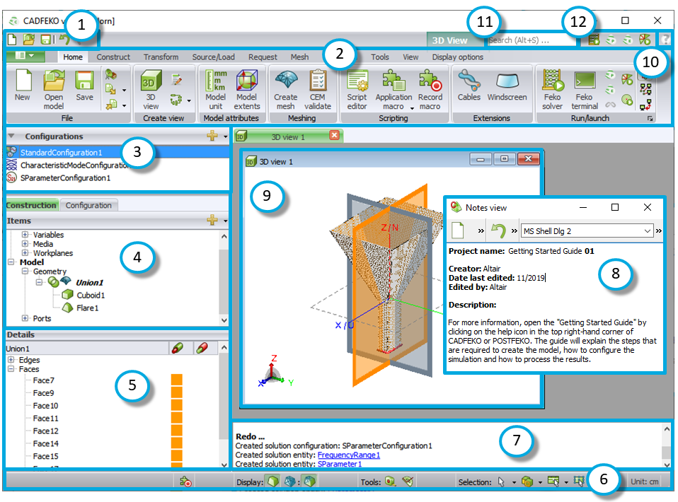
Quick Tour of the CADFEKO Interface View the main elements and terminology in the CADFEKO application window. Figure 1. The CADFEKO window. Quick access toolbar Ribbon Configuration list Model tree Details tree Status bar Message window Notes view 3D view Help Search bar Application launcher