User Interface
Visual guide of the SimSolid Cloud user interface.
Project Dashboard
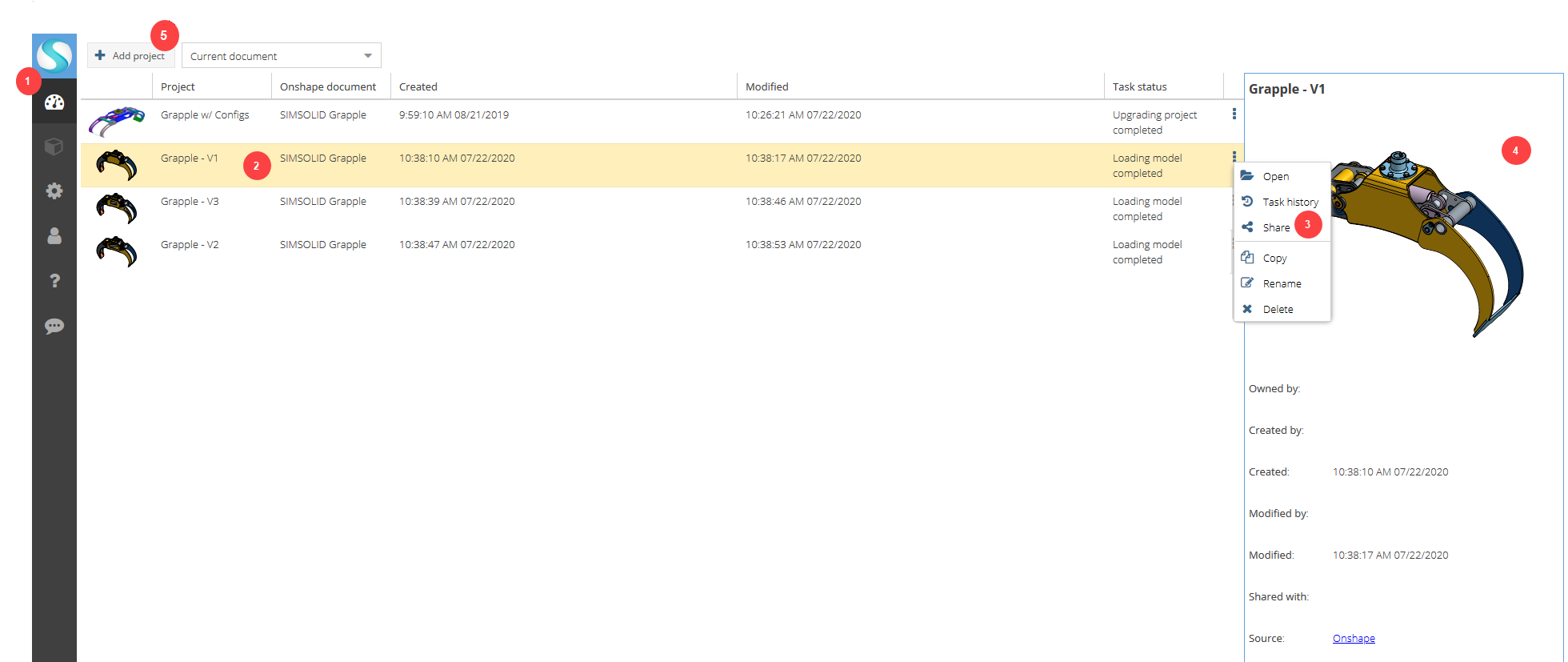
- Icon palette - You can access to the Project dashboard, Project window, your account information, and help on the icon palette. Select the header to expand the icon palette.
- Projects - Projects are listed here. By default, only projects associated with the current geometry file are displayed. To see all projects, open the drop-down menu above the list of projects and select All projects. Pertinent data about the project is given in columns at the top. The columns can be sorted or dragged to reorder. Additional data columns can be added by selecting the pull-down menu found with each column header. Once you select a project, detailed information appears in the panel on the right. You can double-click on a project to open.
- Project action menu - Select
 (Project action button) or right-click on a
project to access actions you can perform.
(Project action button) or right-click on a
project to access actions you can perform. - Detailed information panel - More detailed information about an individual project is displayed here.
- Add project button - Use the Add project button to access the geometry file selector dialog. Select a document and then an element (Part or Assembly) to load the model and create a new SimSolid document.
Project Window
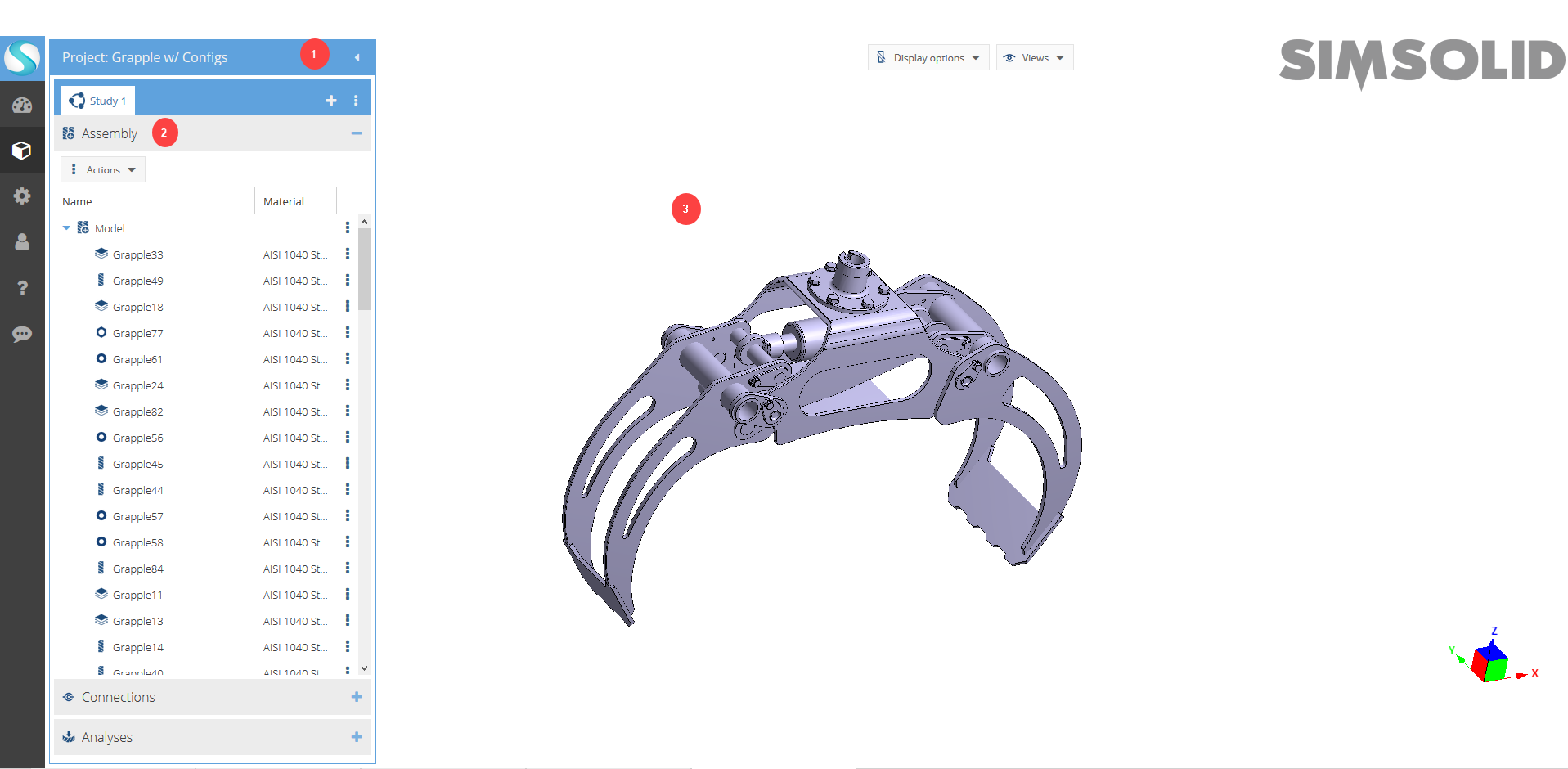
- Project explorer - You can access panels for the current project here. Select the title bar to open or hide the project explorer.
- Panels - Assembly, Connections, and Analysis panels are
where you configure your analysis. You can select the header to open and
close a panel. In the panel, you can select column headers to sort, or drag
columns to reorder. Select (Entity action button) to perform actions on
individual entities. You can also multi-select entities with
Shift +
Control.
- Modeling window - The model is displayed here. You can
select and interact with parts, change display options, and change views in
the modeling window. Use the mouse for model manipulation and object/dialog
list selection. For information about mouse controls, go to Mouse Controls.
With a few limitations, you can also use touch screen monitors with SimSolid Cloud. For more information, go to Touch Screen Monitor Controls.
Change Model View
View the model from different standard views available in SimSolid Cloud.
The following model views are available: Top, Bottom, Front, Back, Left, Right, and Isometric.
-
In the icon palette, click
 Project.
-
Change the orientation of the model in any of the following ways:
Option Description Use the View menu - In the modeling window, click the Views button.
- Select the desired view from the drop-down menu.
Use the coordinate triad Figure 1. 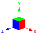
Click any of the block faces to snap that plane parallel to the screen. Double-click to rotate 180 degrees. Define the Top view - On the icon palette, click
 (Settings).
 - Click the Appearance tab.
- For Standard view defaults, select the desired option.
Figure 2. 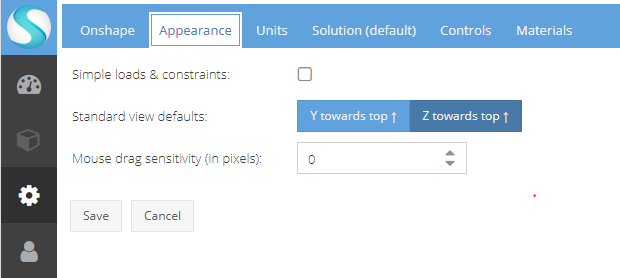
Change Display Options
Choose how parts are displayed in the modeling window.
-
In the icon palette, click
Project.
- In the modeling window, click the Display Options drop-down menu.
-
Select the check boxes for the desired views.
The following display options are available:
- Show hidden parts as ghosts
- Shows hidden parts as transparent but not selectable.
- Show parts translucent
- Renders the model transparent.
- Show parts in random color
- Renders each part with a separate color.
- Zoom view to selected
- Automatically zooms view to the entities selected in the Project Tree.
- Show part edges
- Toggles part edges on and off.
- Show spots
- Toggles spot symbols on and off.
- Show boundary conditions
- Toggles boundary condition symbols on and off.
- Show seam welds
- Toggles seam welds on and off.
- Enable clipping plane
- Clips the assembly with a plane.