Terminology
The following terminology is used in SimSolid Cloud. Note that SimSolid Cloud has both cloud and desktop products. While the terminology is the same, not all features and functions are present in both products. Product differences are highlighted throughout this help document as appropriate.
- Project
- The project is the entire collection of analysis data associated to one design. It can have multiple analyses. In SimSolid desktop, the Project is located in a single name.SSP file. In SimSolid Cloud, the project is located on the cloud and Privacy levels are defined to control access. Projects are by default private but access may be granted to other parties on an individual, group or global (public) level.
- Design studies
- The primary goal of design-analysis is to evaluate the effect of design changes on the product’s performance. In SimSolid Cloud, design studies are used to collect and quantify design variations. Designs studies are defined as a set of part geometry, part connections and one or more analysis definitions along with their corresponding analysis results. Each design study can contain a complete CAD assembly containing hundreds of parts and each SimSolid Cloud project can contain many design studies.
- Model
-
The model is defined to be the set of CAD geometry to be analyzed. This consists of the full assembly, sub-assembly, part and part face tree structure that in found in the accompanying CAD system. However, facets and not surfaces are used to define the boundary representation. This make geometry handling more efficient. Parts are faceted on the fly during CAD import. The SimSolid Cloud facet parameters can be found in CAD preferences tab.
Note that in many cases, SimSolid Cloud is capable of analyzing the full geometric representation without simplification and model clean-up. This makes it much easier to process design geometry as compared to other more traditional FEA systems.
- Material properties
- Material properties define the structure and thermal characteristics of
each part. In SimSolid Cloud, materials are assumed to
remain in the linear-elastic region of the stress-strain curve for
structural analysis. That is, strains are assumed small (<0.2%) and
material properties do not change with load or time.
Figure 1. 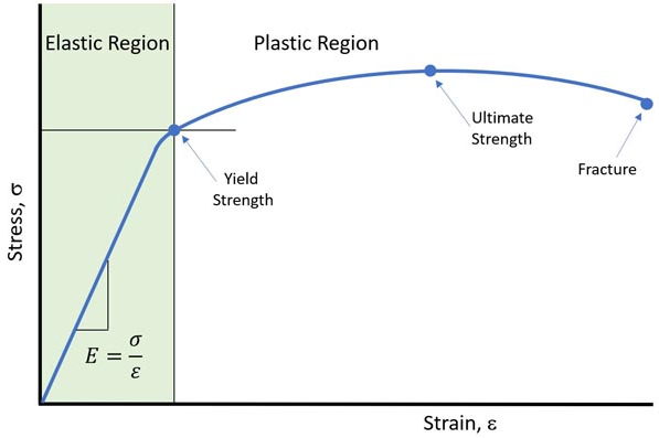
For structural analyses, only density, Young’s modulus and Poisson’s ratio must be defined. Additionally, material yield strength is used to calculate factors of safety. For thermal analysis, only thermal conductivity and the coefficient of linear expansion are required.
SimSolid Cloud comes with a sample material database which defines these parameters for common materials (steel, aluminum, etc.). Custom material properties can be created as well. Click for how to do it.Important: Material properties can dramatically effect simulation solution results. Material properties provided with SimSolid Cloud are intended as examples only. Actual material properties should be obtained from the relevant part or material supplier and entered in a local user database. SimSolid Cloud Corporation does not verify or validate the accuracy of the examples materials provided. - Connections
- Connections define the regions of contact between parts in an assembly. In SimSolid Cloud, connections can be found automatically using two distance tolerances which define the allowable gaps and penetration between parts. A strength of SimSolid Cloud is that parts do not have to line up exactly. The user can simply adjust the two tolerances to find an acceptable connection region. In SimSolid Cloud, there are both standard (bonded, sliding, separating) connections as well as spot welds.
- Contact conditions
-
Contact conditions are used to establish relationships in the connection region between contacting parts within an assembly. In SimSolid Cloud, contact conditions can be defined as the following
- Bonded contact – used to connect parts that act as if they were bonded and stuck together. Loads between the parts are fully transferred, and bonded components never separate from each other during the analysis
- Sliding contact – allows the parts to slide relative to each other in the local tangential plane, while not allowing either inter-penetration or separation of the connected surfaces. Only normal to the surface forces are transferred between the parts.
- Disable contact – the parts act if they were disconnected, i.e. they may separate from each other or even inter-penetrate into each other under the load. The applied forces do not transfer through the disabled contact.
- Separating contact – the parts may partially or completely separate from each other under the load. The forces transfer only through the connected regions. Friction coefficient defines the sticking/sliding threshold. The friction coefficient must be between 0.0 and 1.0. Typical values are 0.1 to 0.2. Value of 0 indicates sliding and 1 indicates bonded. This is a non-linear solution and takes more time than simple bonded or sliding contact.
- Constraints
-
Structural constraints restrict or limit the movement in specified regions of the model. For static analyses, models much be sufficiently constrained such that all rigid body motion is removed. Rigid body motion is defined as translation or rotational movement along or about the 3 primary (X, Y and Z) geometric axes. In SimSolid Cloud constraints can be the following:
- Immovable – Immovable constraints enforces zero translational displacements in all directions.
- Sliding – Sliding constraints enforces zero displacement in directions normal to the surface direction. Displacements tangent to the surface are unconstrained.
- Hinge – Hinge constraint can only be applied to full or partial cylindrical faces. The cylindrical faces may be either concave or convex. The hinge constraint allows free rotation about the centerline of the cylindrical faces but constrain movement in both the radial and axial directions.
- Spring – Spring constraints can be thought of as elastic foundations that apply stiffness coefficients between the structure and ground.
- Loads
-
Structural loads are forces applied to a part or assembly face and cause the model to displace, deflect, and induce stresses and strains.
In SimSolid Cloud loads can be the following:- Pressure – A pressure load is defined as force per unit area. Pressure is assumed to be constant and may be applied to part faces.
- Bearing – Bearing loads are sinusoidal varying pressure loads applied to cylindrical faces.
- Force/Displacement – Force &/or prescribed displacement is defined as a load on the model. The specified value is interpreted as a total force applied to all selected part faces.
- Gravity – Gravity is a body load uniformly distributed over the volumes of parts of an assembly. The direction of gravity is always defined in the global X, Y or Z reference frame.
- Inertia – A inertia load is a body load uniformly distributed over either a group of part or the entire assembly. In SimSolid Cloud Cloud, inertia loads may be translational or rotational.
- Inertia relief – Inertia relief is applied to a structure in order to simulate deformations and stresses in cases where (1) the structure is unconstrained so it can move as a rigid body and (2) an active load is suddenly applied to the structure, so the structure starts moving with translational and rotational accelerations. Typical applications of inertial relief are an airplane in flight or a satellite in space.
- Remote – Remote loads are used to apply distributed loads to select set of faces that are statically equivalent to a load applied to a single remote point. Static equivalency means that the applied traction exerts the same effect on the model as the force and/or moment applied to the selected point. The remote load is the only method for applying bending, twisting, or other moment loads to your model.
- Bolt/nut tightening – Bolt/nut tightening loads are used to simulate pre-tensioning. These loads are applied directly to full 3D bolts and nuts and can be specified by nut turns, bolt torque or target axial load values. A wide variety of bolted configurations are supported including blind bolts, nuts on threaded shafts, and nuts on posts.
- Thermal – either a constant temperature can be specified or a temperature distribution from a previous thermal analysis can be applied.
- Distributed mass - Used to apply distributed mass across selected faces. Distributed mass can be applied using total mass or mass per area.
- Analyses
-
Analyses are numerical processes that take model inputs (geometry, materials, constraints, loads, etc.) and calculates performance results (displacements, stresses, strains, reaction forces, etc.).
In SimSolid Cloud, the following analysis types are available:- Linear static – linear static assumes the model is loaded slowly (static) and stresses do not exceed the yield strength of any part material (linear). This is the most common analysis type.
- Geometric non-linear static – assumes the model is loaded slowly. Displacements can be large but strains remain small below the elastic limit of the material.
- Modal – Modal analysis in structural mechanics is used to determine the natural mode shapes and frequencies of an object or structure during free or fixed vibration.
- Thermal – Thermal predicts how thermal effects propagate through the model. In SimSolid Cloud, thermal analysis assumes a linear steady state condition. That is, the temperatures do not vary with time (steady state) and the material property remains constant.
- Results
-
Results provide performance insight for the simulation.
In SimSolid Cloud, the following result displays are available:- Contour plots – Plots the distribution of a result entity over the geometric domain as banded colors. Structural quantities that can be plotted include displacements, stresses, strains and safety factors. Contours can be 6, 12 or continuous color bands.
- Reaction forces – These are resultant forces/moments at structural supports and/or contact areas in part connections.
- Bolt/nut forces - You can view a table of resultant forces in both tightened and not tightened bolts and nuts.