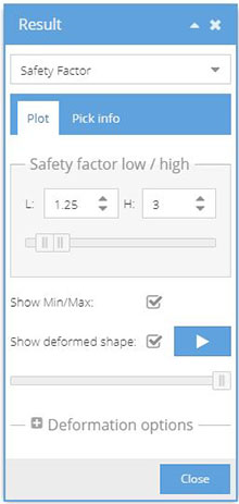
Overview of the display options and controls for Safety factor contours.
Safety factor contours are presented in 3 color bands (red, yellow and blue). The
threshold between bands are controlled by the Safety Factor LOW and Safety Factor
HIGH values. The factors act as multipliers on the criterion value and reflect the
degree of uncertainty that the user is looking to tolerate. For example, a LOW
safety factor value of 1.25 indicates a 25% safety margin on the failure criterion
value.Figure 1.
Update the LOW or HIGH fields to change the threshold values. You can
manipulate the threshold values in real time using the slider in the
dialog.
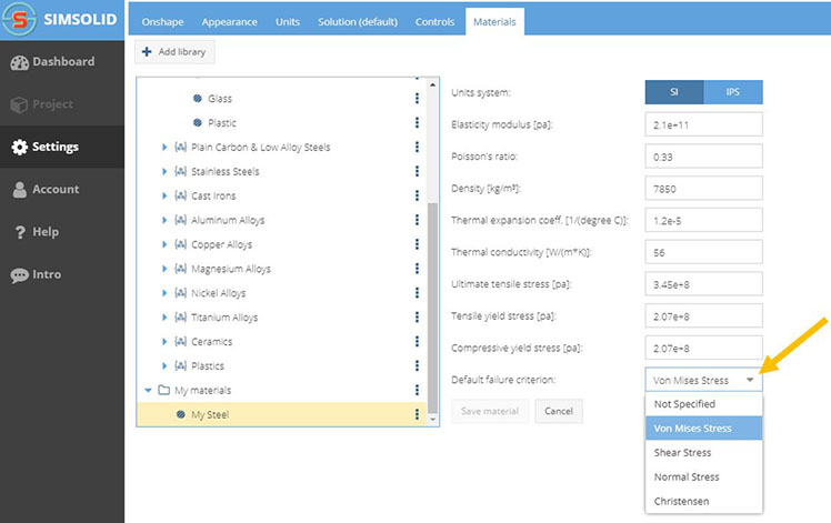
To change the failure, you must edit the material property definition in the
material database. The Standard database is read only and cannot be edited,
so you will need to create a new database and copy materials. Learn more
about manipulating materials here.
Change the default criterion from the Material database.Figure 2. Safety factors are not plotted for materials with Not Specified
failure criterion.
Note: When assigning materials, SimSolid Cloud makes a local copy of
each material property in the project file. Changes to material properties in
the database are not updated in the model. You must reapply the material and
rerun the analysis to see this change.
Potential Material Failure Analysis - Safety Factor
Safety factor plots are used to characterize zones of possible material
failure.
Failure Criterion
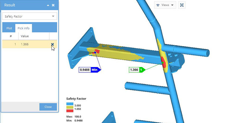
SimSolid Cloud safety factor plots are used to characterize zones of
possible material failure. The are simple three color contours that highlight areas
of possible material yielding. In SimSolid Cloud, static structural
analysis is linear elastic, so areas where the material yields should be recognized
and designed out.Figure 3.
Different failure criteria can be calculated quickly and the results dynamically
updated. The material failure condition is expressed by the following inequality:
Criterion Value < 1
If the inequality is met, the material is considered safe. Criterion Value depends on
the stress state of the material at a given location. Safety Factor is the inverse
to the Criterion Value. Dividing both sides of the inequality by the Criterion
Value, one obtains the failure condition expressed through the Safety Factor:
Safety Factor = 1/Criterion Value
Note: Proper failure criterion is material and application specific. It also
reflects the degree of conservatism considered appropriate for the particular
design. While default criterion are provided for each SimSolid material, they should be considered as examples
only. The ultimate decision of which criterion to use is the responsibility of
the design engineer.
Safety Zone Contours in SimSolid
Safety zone contours are presented in 3 color bands (red, yellow and green). The
threshold between bands are controlled by the Safety Factor Low and Safety Factor
High values. The factors act as multipliers on the criterion value and reflect the
degree of uncertainty that you are looking to tolerate. For example, a safety factor
value of 1.25 indicates a 25% safety margin on the failure criterion value.
Failure Theories
Failure theories are material specific and their formulation is dependent on the type
of material being considered.
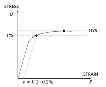
Ductile Materials
In ductile materials, failure takes place by yielding. Ductile materials
includes most metals and some plastics. The material tensile yield
strength (TYS) is used to determine the working stress. Prior to yield,
material response is assumed to be elastic.Figure 4.
Many steels, especially heat-treated materials, do not have a
well-defined elastic limit. In this case, the yield strength is
usually defined at the point where the plastic strain is about 0.1%
to 0.2%
CAUTION:
Steel is often thought of as a ductile material. However this is
not always the case. At low temperatures on the order of 20°to
40° F (-7° to 5° C) many steels begin to lose their ductile
properties. Below some transition temperature, you can no longer
treat steel like a ductile material.
It is recommended that you contact the material supplier for best
practices on how to determine material failure.
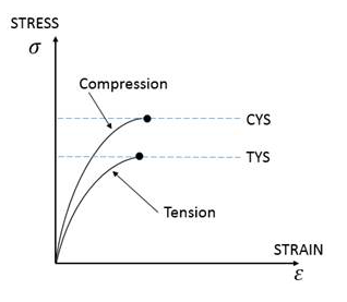
Brittle Materials
In brittle materials, failure takes place by fracture, therefore the
criteria of failure is different from that for ductile materials. The
fracture stress in compression is much larger than that in tension.Figure 5.
The failure theories available in SimSolid are as
follows:
Max von Mises Stress
Most appropriate for ductile materials, this theory is also known as
the maximum distortion energy criterion, octahedral shear stress
theory or Maxwell-Huber-Hencky-von Mises theory. It is computed as
the ratio of the material’s tensile yield strength to the von Mises
stress and is usually considered to be the best fit with experiment
results.
Max Shear Stress
Most appropriate for ductile materials, this theory is also known as
Tresca's or Guest's criterion. It states that yielding begins whenever
the maximum shear stress in the model becomes equal to the maximum shear
stress in a tension test specimen that has begun to yield. As compared
to the Max von Mises Stress theory, Max Shear Stress is a more
conservative approach. In some cases, it can over-estimate stress by
15%.
Max Normal Stress
Most appropriate for brittle materials, this theory is also known as
Coulomb’s criterion. It is computed by examining the ratio of the
material’s tensile and compressive strength to the max principal
stresses.
Christensen
This is a more recent theory that tries to bridge the gap between
failure criteria for ductile and brittle materials. The Christensen
failure criterion is composed of two separate subcriteria representing
competitive failure mechanisms. One has a quadratic form similar to the
von Mises criterion and the other is a Coordinated Fracture criterion
similar to the Coulomb-Mohr criterion.