Conversion
3D Antenna Patterns
In contrast to the proprietary binary files, the ASCII antenna pattern file (.apa) can also be edited using a simple ASCII editor.
The ASCII format allows comment lines which must start with “#” as the first character. All lines starting with a “#” are ignored when reading the patterns. The values of the pattern are organized in lines, one value per line. The theta angle values run from 0° to 180°; the phi angle values cover the range between 0° and 360°. The sequence of pairs in the ASCII file and the increment of the angles can be chosen arbitrary – ProMan sorts them in the correct order and interpolates missing values based on the neighboring values.
# Theta         Phi         gain (Theta, Phi) [dB]

0 90 -7.0
0 180 -12.0
0 270 -7.0
0 360 -2.0
90 0 5.0
90 90 0.0
90 180 -5.0
90 270 -7.0
90 360 5.0
180 0 -2.0
180 90 -7.0
180 180 12.0
180 270 -7.0
180 360 -2.0
The main direction of radiation of the antenna (as defined within ProMan) is in the direction of theta = 90 degrees and phi = 0 degrees.
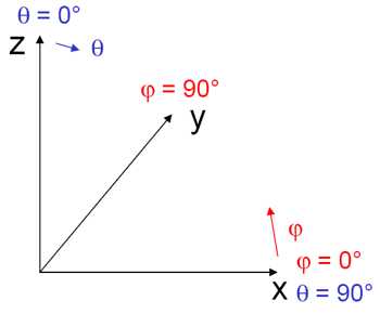
Figure 1. The main direction of radiation of the antenna as defined in ProMan.
2D Antenna Patterns
3D patterns can also be interpolated based on 2D patterns. If only the vertical and the horizontal plane are available, both planes can be defined in ASCII files: .aha for horizontal patterns (antenna horizontal ASCII) .ava for vertical patterns (antenna horizontal ASCII).
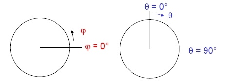
Figure 2. Top view of a horizontal pattern (on the left) and side view of a vertical pattern (to the right).
The file formats are similar to the format of the 3D pattern, but only one angle value per line is allowed. Also the number of values in the file is required in the first data line.
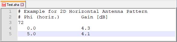
Figure 3. Sample of a .aha file.