Virtual Connector - Joints
Create joints in SimSolid.
Purpose
SimSolid performs meshless structural
analysis that works on full featured parts and assemblies, is tolerant of
geometric imperfections, and runs in seconds to minutes. In this tutorial,
you will do the following:
- Learn how to create joints - hinge, linear guide, and virtual pins.
Model Description
The following model file is needed for this tutorial:
- Joints_Hinge_LinearGuide.ssp
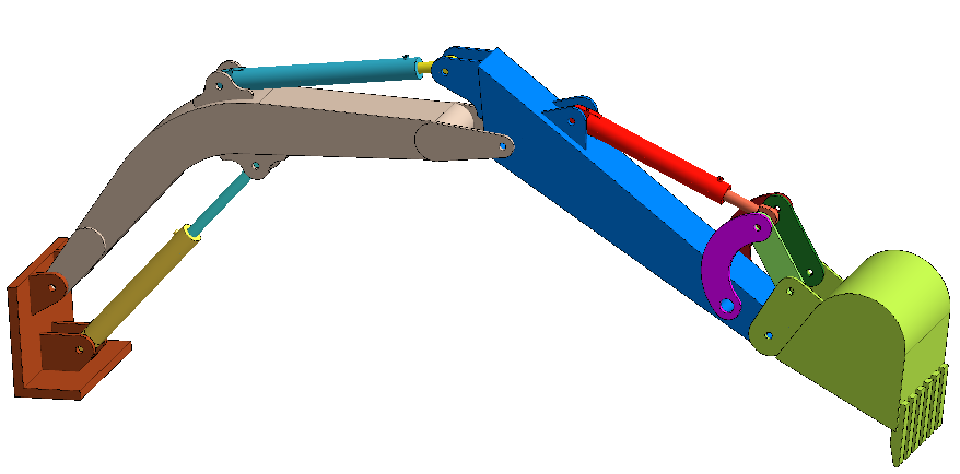
Figure 1.
This file has the following specifications:
- Material is set to Steel for all parts.
- Modal analysis is pre-defined.
Open Project
Open the SimSolid project file.
-
Click the
 (Open Project) icon.
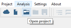
Figure 2.
Create Hinge Joints
Create hinge joints on selected faces.
-
On the Connections workbench, select
 > Joints.
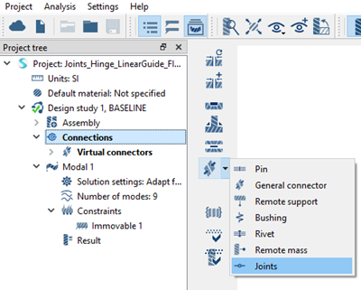
Figure 3. -
In the modeling window, select the faces as shown in
orange in Figure 4.
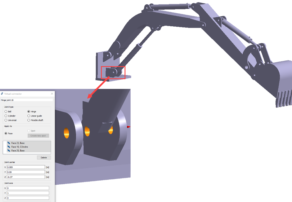 Figure 4. Joint center and axis are automatically picked based on selected faces. The values can be edited if needed.
 -
Repeat steps 1
through 4 to
create hinge joints at the locations shown in Figure 5.
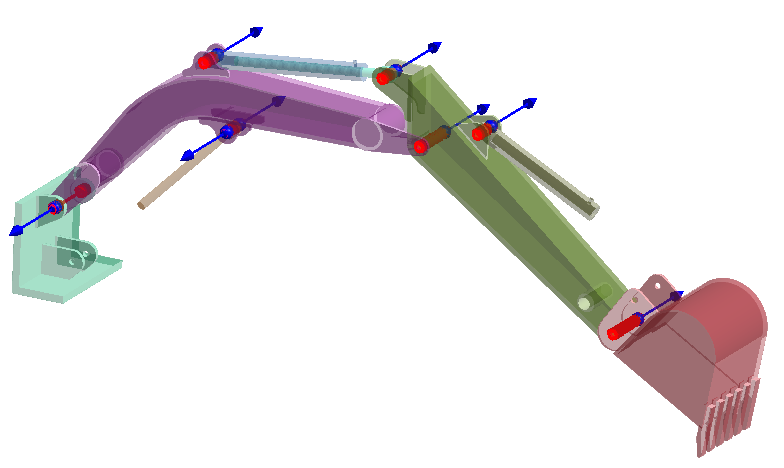 Figure 5.
Create Linear Guide Joint
Create a linear guide joint on selected faces.
-
On the Connections workbench, select > Joints.
-
In the In the modeling window, select the faces as
shown in orange in Figure 6
- Select Face 6, part6 first.
- Right-click on Face 6, part6 and select from the context menu.
- Select Part 21, Cilindro.
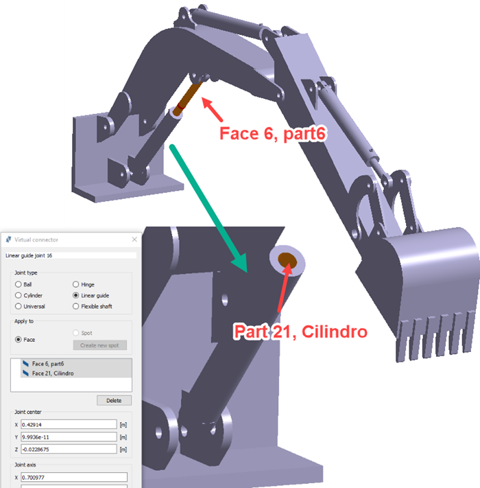
Figure 6.Joint center and axis are automatically picked based on selected faces. The values can be edited if needed. -
Repeat steps 1
through 4 to
create linear guide joints at the locations shown in Figure 7.
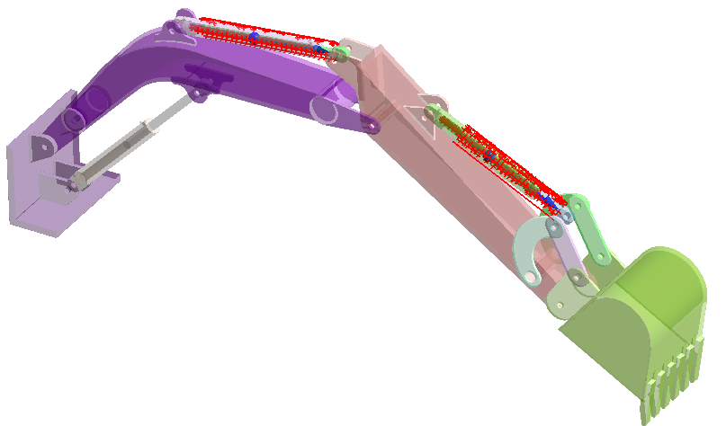
Figure 7.
Create Virtual Pin
Create a virtual pin on selected faces.
-
On the Connections workbench, select > Pin.
-
In the In the modeling window, select the faces as
shown in orange in Figure 8.
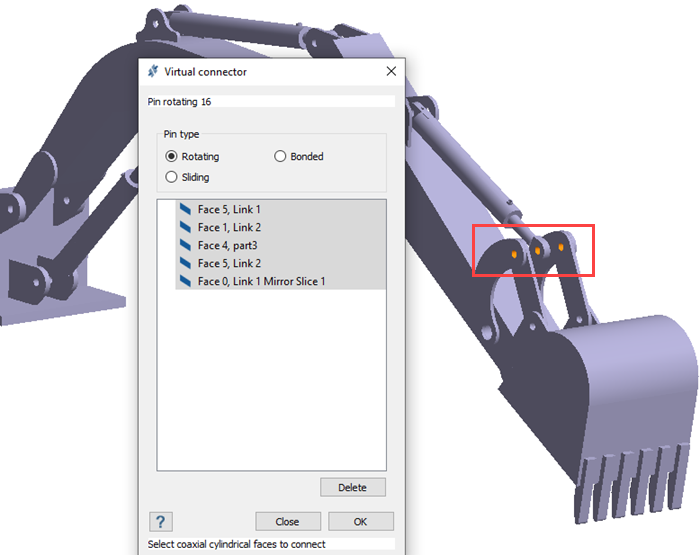
Figure 8. -
Repeat steps 1
through 4 to
create virtual pins at the locations shown in Figure 9.
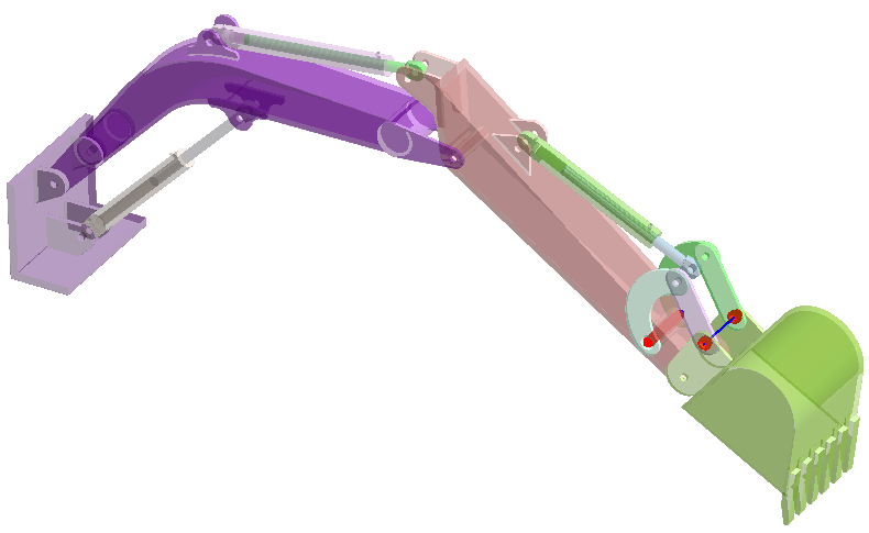
Figure 9.Note: The differences between a hinge joint and a virtual pin are as follows:- Hinge joints allow only rotation about the said axis whereas pins can be rotating/bonded/sliding.
- Virtual pins are used to only connect cylindrical faces whereas hinge joint doesn’t have a restriction on the type of face.
- Virtual pins can connect more than two parts whereas Joints are limited to two parts.
Review Connections
Find disconnected groups of parts in the model.
-
On the Connections workbench, click
 (Find and show disconnected groups of parts).
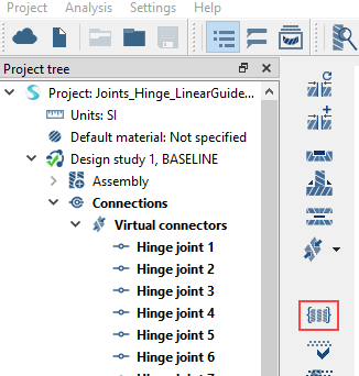
Figure 10.A message appears stating that the model has no disconnected groups of parts.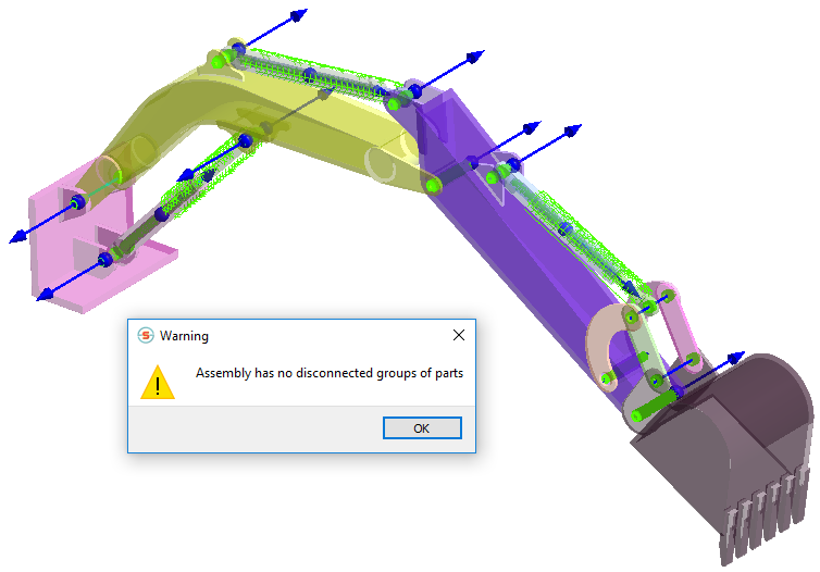
Figure 11.
Run Analysis
Solve the analysis.
- In the Project Tree, open the Analysis Workbench.
-
Click
 (Solve).
Review Results
Plot the displacement contour.
-
On the Analysis workbench toolbar, click the
 (Results plot) icon.
-
Select Displacement Magnitude.
The Legend window will open and display the contour plot. The Frequency (Hz) window will open and display the modes.
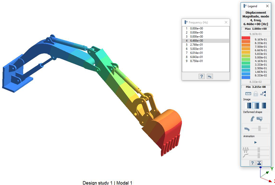 Figure 12.