Rivets
Create Rivets in SimSolid.
Purpose
SimSolid performs meshless structural
analysis that works on full featured parts and assemblies, is tolerant of
geometric imperfections, and runs in seconds to minutes. In this tutorial,
you will do the following:
- Learn how to create Rivets from CSV import and graphical picking on a point.
Model Description
The following model file is needed for this tutorial:
- Rivets.ssp
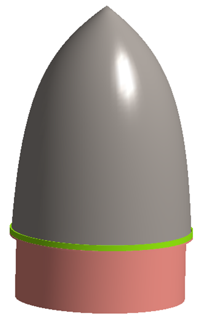
Figure 1.
This file has the following specifications:
- Material is set to Aluminum for all parts.
- Modal Analysis is defined.
Open Project
Open the SimSolid project file.
-
Click the
 (Open Project) icon.
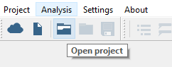
Figure 2.
Import Rivets
Import rivets from a CSV file.
-
On the Connections workbench toolbar, select
 > Rivet.
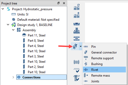
Figure 3. -
In the File Explorer, browse to the Rivets_rocketNose.csv
file and click Open.
All valid rivets are shown in black in the dialog. Failed rivets are highlighted in red in the dialog and black in the modeling window.
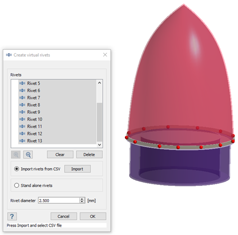
Figure 4.
Create Standalone Rivets
Create rivets by picking points on the model.
-
On the Connections workbench toolbar, select > Rivet.
- Optional:
Under Coordinates of rivet entity, you can edit the location of the rivet by
entering coordinates for X, Y, and Z.
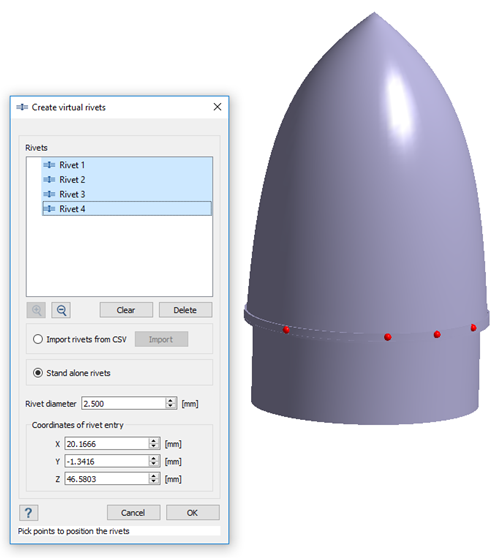
Figure 5.
Find Disconnected Groups
Find and fix disconnected groups of parts in the model.
-
On the Connections workbench, click
 (Find and show disconnected groups of parts).
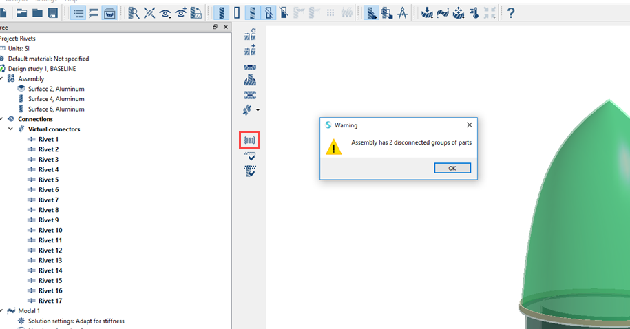
Figure 6.A message appears stating that the model has disconnected groups of parts. -
In the Disconnected groups of parts dialog, select both
groups listed and click Connect.
A dialog will open promting you to create automatic connections.
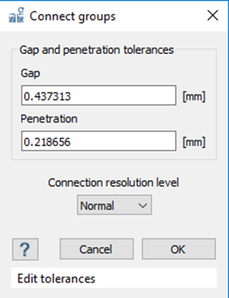
Figure 7.
Run Analysis
Solve the analysis.
- In the Project Tree, open the Analysis Workbench.
-
Click
 (Solve).
Review Results
Plot displacement magnitude contour.
-
On the Analysis Workbench, select
 > Displacement Magnitude.
The Legend widow will open and display the contour plot. The Frequency (Hz) window will open and list the modes.
> Displacement Magnitude.
The Legend widow will open and display the contour plot. The Frequency (Hz) window will open and list the modes.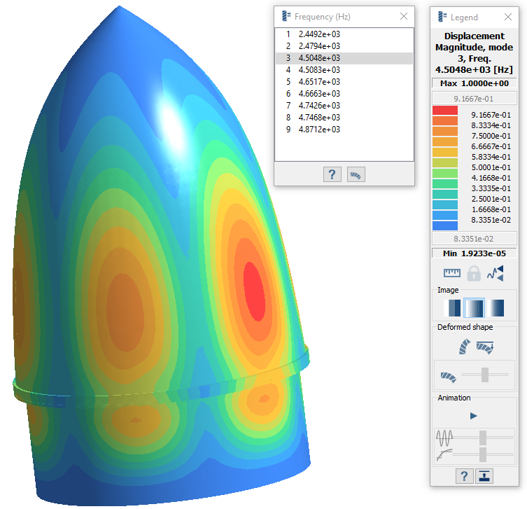
Figure 8.