Perform a static structural analysis of a pullup bar assembly.
Purpose
SimSolid performs meshless structural
analysis that works on full featured parts and assemblies, is tolerant of
geometric imperfections, and runs in seconds to minutes. In this tutorial,
you will do the following:
Learn how SimSolid works
Create a comparison for SimSolid's workflow and results
with those obtained with traditional FEA.
Model Description
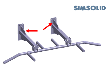
There are two different pullup bar models used in this tutorial. Each model has 33
parts. You will perform two static structural analyses for the following:
2 load cases of 750N (168 lbf) total load on different handle locations
2 different design configurations with varying support brackets
The following model files are needed for this tutorial:
Pullup bar V1.x_t
Pullup bar V2.x_t
Figure 1.
Import Geometry
Import model geometry into SimSolid.
Open a new SimSolid session.
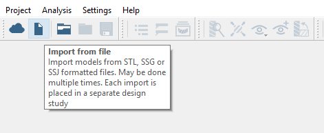
Click the (Import from file) icon.
Figure 2.
In the Open geometry files dialog, choose
Pullup bar V1.x_t.
Click Open.
The assembly will load in the modeling window.
An Info window will appear
warning that overlapping parts were detected. The Review
overlapping parts dialog will also open.
Close the Info window, then
Close the Review overlapping parts
window.
Create Connections
Specify gap and penetration tolerances to create automatic connections.
In the Project Tree, click
on the Connections branch.
In the Connections workbench toolbar, click (Automatic connections).
Specify Gap and Penetration tolerances as 1.
Set Connection resolution level to Increased.
Click OK.
Note:
SimSolid will create connections even in areas with overlapping
geometry.
SimSolid will automatically identify bolts, nuts and washers.
Sliding contact will be applied automatically in bolt shanks,
bonded otherwise.
Assign Materials
Apply materials to all parts in the assembly.
In the Project Tree, click on
the Assembly branch.
In the Assembly workbench, click (Apply materials).
Pick Steel from the Generic materials list.
Click Apply to all parts.
Click Close.
In the Assembly branch of the Project Tree,
material properties are identified for each part.
Create Structural Linear Analysis
Create a structural linear analysis with immovable constraints and a handlebar
load.
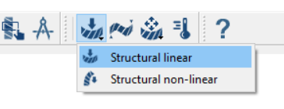
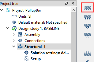
On the main window toolbar, click (Structural analysis).
Choose Structural linear.
Figure 3.
The new analysis will appear in the Project Tree
under Design study 1 and the Analysis Workbench will
open.
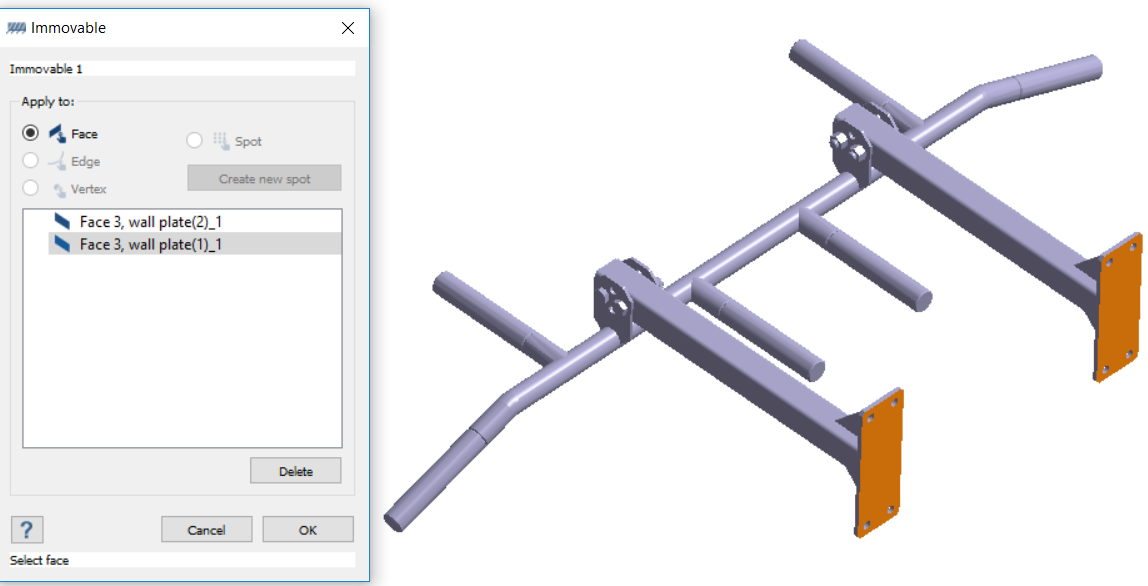
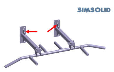
Create Immovable Support
Create immovable supports on the wall faces in the pullup bar model.
In the Analysis Workbench, click (Immovable support).
Figure 4.
In the dialog, verify the Faces radio button is
selected.
In the modeling window, select the two faces shown in
orange in Figure 5.
Figure 5.
Click OK.
The new constraint, Immovable 1, will appear in the Project Tree. A visual representation of the straint will
appear on the model.
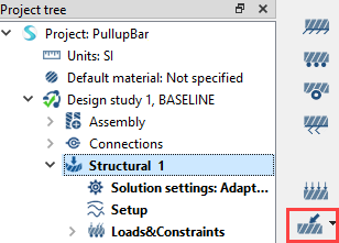
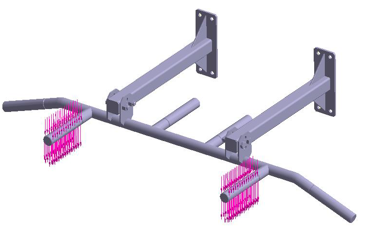
Create Force Loads
Create handlebar loads on the pullup bar model.
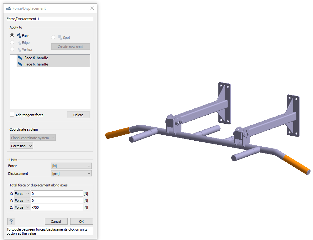
In the Analysis Workbench, click (Force/Displacement).
Figure 6.
In the dialog, ensure the Faces radio button is
selected.
In the modeling window, select the two handle faces
shown in orange in Figure 7.
Figure 7.
Specify a Z direction force of -750 N.
Click OK.
The new force, Load/Displ. 1, will appear in the Project Tree. Vectors representing the load will appear on
the model.
Create Second Structural Linear Analysis
Create a copy of an analysis and edit loads.
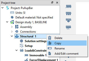
In the Project Tree, right-click on
Structural 1.
Choose Copy from the context menu.
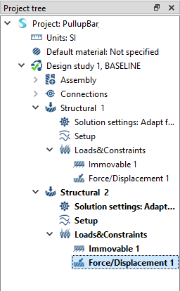
The Structural 2 analysis will appear in the Project Tree. Figure 8.
Click next to Structural 2 to expand the analysis
branch.
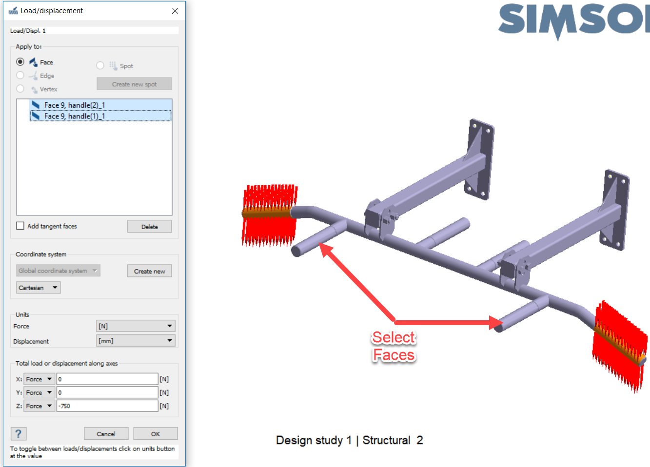
Edit the handlebar loads.
Double-click on the Load/Displ. 1 load under
Structural 2.
Figure 9.
In the Force/Displacement dialog, select the faces
currently listed and pick Delete.
In the modeling window, choose the two front
handle faces.
Figure 10.
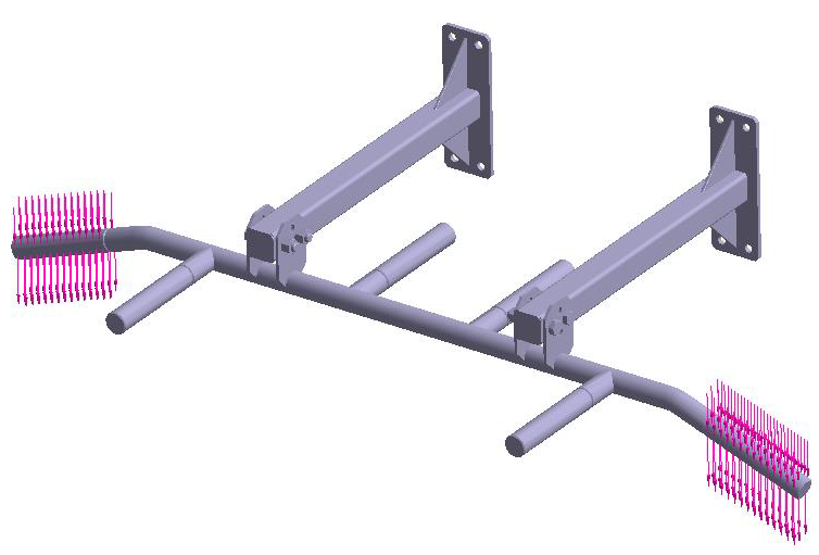
Click OK.
Vectors representing the load will appear on the model. Figure 11. Load case 1 Figure 12. Load case 2
Run Design Study
Solve all analyses in the design study.
In the Project Tree, click the desired
Design study branch.
Click (Solve).
SimSolid will run all analyses in the design study
branch. When finished, a Results branch for each analysis will appear in the
Project Tree.
Compare Results with Bookmarks
View results from analysis and create results images/animations.
In the Project Tree, select the
Results branch for Analysis 1.
On theAnalysis Workbench, click (Results plot).
Select the Displacement Magnitude plot.
In the Legend window, click (Show deformed shape).
The modeling window will update to show the
chosen results and display options.
Click the (Snap bookmark) icon.
SimSolid will save the data currently
displayed in the modeling window as an image or
animation, and a thumbnail will appear in the Bookmark browser. You can select a
bookmark at any tine to display a saved view in the modeling window. Figure 13.
Toggle between the different results using the Bookmark browser.
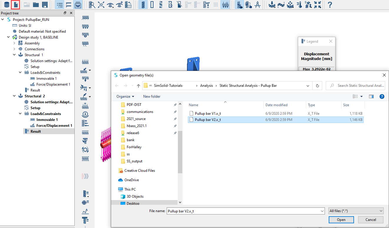
Create Second Design Study
In your project, create a second design study with new geometry.
The new geometry is almost identical to that of Study 1. The only difference is the
design of the vertical support brackets. SimSolid instances
identical geometry to minimize resources required; this makes the database smaller and
the solutions faster.
Repeat the Import Geometry step and load the file
Pullup bar V2.x_t.
The new geometry is read into a second design study. All analysis
definitions will be copied from Study 1 to Study 2. Conflicts and
inconsistencies are flagged in red in the Project Tree.
This tutorial does not require you to fix geometric inconsistencies. Figure 14.
Note: New parts in the assembly will not yet have materials
assigned.
Figure 15. Design Study 1 Figure 16. Design Study 2
Add Connections for New Parts
Create connections for new parts in the second Design Study.
Close the part overlap warning and review dialog.
In the Add connections for new parts dialog, specify gap
and penetration tolerances as 1.
For Connection resolution, select Increased.
Click OK.
Assign Materials
Apply materials to all parts in the assembly.
In the Project Tree, click on
the Assembly branch.
In the Assembly workbench, click (Apply materials).
Pick Steel from the Generic materials list.
Click Apply to all parts.
Click Close.
In the Assembly branch of the Project Tree,
material properties are identified for each part.
Run Design Study
Solve all analyses in the design study.
In the Project Tree, click the desired
Design study branch.
Click (Solve).
SimSolid will run all analyses in the design study
branch. When finished, a Results branch for each analysis will appear in the
Project Tree.
Compare Results
In the Bookmark browser, click a thumbnail to load a saved results view.
In the Project Tree, click on any
Results branch.
The modeling window will update with the results
from the chosen analysis. You can click on other Results branches to rapidly
switch between views.
View Reaction Forces
View reaction forces on selected parts of the assembly.
In the Project Tree, open
the Analysis Workbench.
In the workbench toolbar, click the (Reaction/contact force) icon.
Click the Supports, Connections,
or Parts tab.
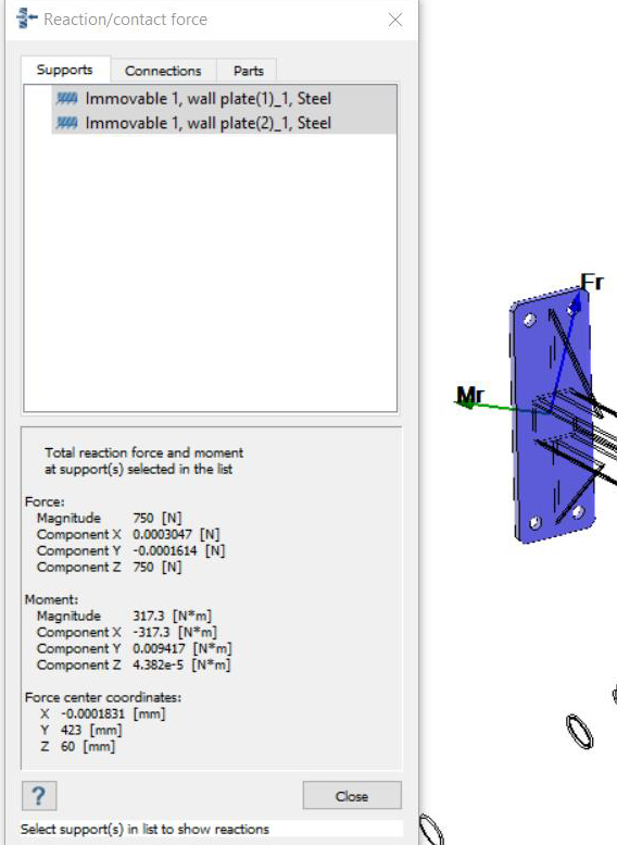
A summary table of the reactions will open. Moment vectors will be
displayed in the modeling window. Figure 17.
Optional: Select a single support, connection, or part to view forces on a single
element.
Optional: Select multiple supports, connections, or parts to view a summary of
forces.
Compare with Traditional FEA
Run the same analysis using your existing traditional FEA application.
Use the model files to run this same analysis with your traditional FEA
application.
Important:
Do not merge or simplify geometry, use bonded and sliding contact
same as SimSolid.
Check for part overlaps
Make sure elemetn density is acceptable for smaller parts
Compare the following between the two programs:
Solution quality
Number of workflow steps required
Time required to mesh
Time required to solve
Time required to examine results
Time required to refine and rerun model
Refine Solution Settings
Adjust SimSolid's solution settings for specialized
analyses.
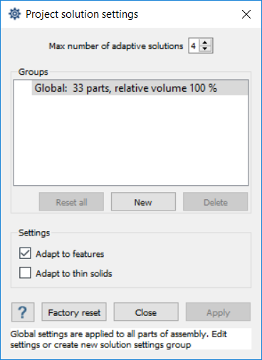
In the Project Tree, double-click on
Solution settings.
In the dialog, increase Max number of adaptive solutions to
4.
Activate the Adapt to features checkbox.
Click OK.
Figure 18.
In the Project Tree, select the
Project.
Click (Solve).
Examine the changes in results.
Compare with Pass 3 results.
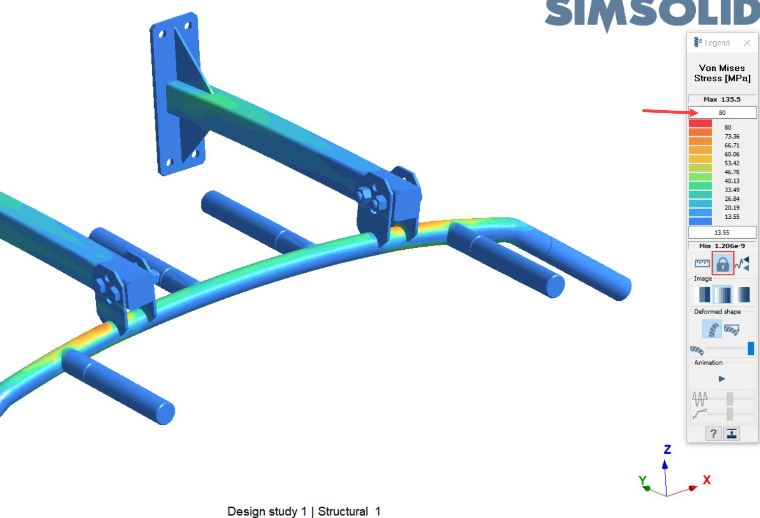
In the Analysis Workbench, select > Von Mises Stress.
In the Legend, in the box under Max, enter
80.
This will adjust (lock) the legend to be similar to a 3 pass
solution and will better highlight peak stress areas.
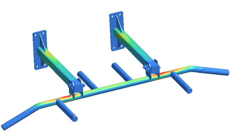 Figure 1.
  (Import from file) icon.
 (Automatic connections).
 (Apply materials).
 (Structural analysis).
 (Immovable support).
 (Force/Displacement).
 next to Structural 2 to expand the analysis
branch.
next to Structural 2 to expand the analysis
branch.
 (Solve).
SimSolid will run all analyses in the design study branch. When finished, a Results branch for each analysis will appear in the Project Tree.
(Solve).
SimSolid will run all analyses in the design study branch. When finished, a Results branch for each analysis will appear in the Project Tree. (Results plot).
 (Show deformed shape).
The modeling window will update to show the chosen results and display options.
(Show deformed shape).
The modeling window will update to show the chosen results and display options. (Snap bookmark) icon.
SimSolid will save the data currently displayed in the modeling window as an image or animation, and a thumbnail will appear in the Bookmark browser. You can select a bookmark at any tine to display a saved view in the modeling window.
(Snap bookmark) icon.
SimSolid will save the data currently displayed in the modeling window as an image or animation, and a thumbnail will appear in the Bookmark browser. You can select a bookmark at any tine to display a saved view in the modeling window.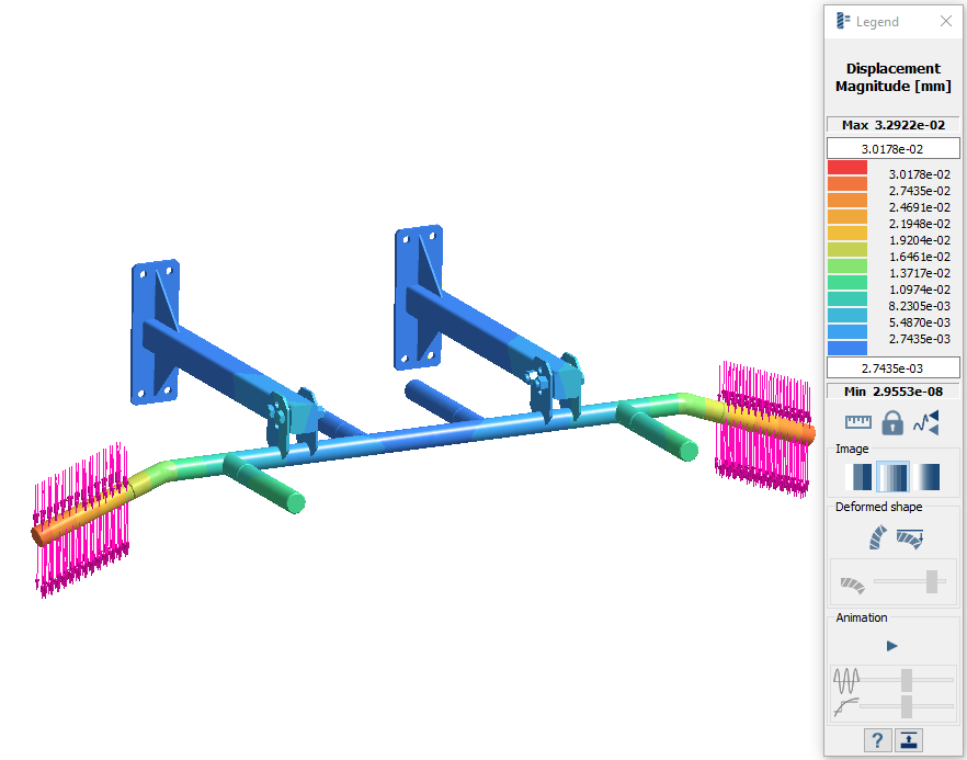
 (Reaction/contact force) icon.
 (Solve).
 to reset the legend to default
values.
to reset the legend to default
values.