SimSolid performs meshless structural
analysis that works on full featured parts and assemblies, is tolerant of
geometric imperfections, and runs in seconds to minutes. In this tutorial,
you will do the following:
Learn how SimSolid works.
Setup a thermal analysis in SimSolid.
Model Description
The following model file is needed for this tutorial:
cup.ssg
Import Geometry
Import model geometry into SimSolid.
Open a new SimSolid session.
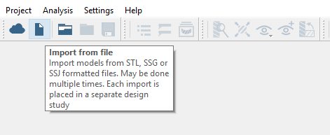
Click the (Import from file) icon.
Figure 1.
In the Open geometry files dialog, choose
cup.ssg.
Click Open.
The assembly will load in the modeling window.
Assign Materials
In the Project Tree, click on
the Assembly branch.
In the Assembly workbench, click (Apply materials).
In the dialog, click to expand the Copper Alloys folder.
Pick Electrolyte tough pitch Copper from the list.
Click Apply to all parts.
Click OK.
In the Assembly branch of the Project Tree,
material properties are identified.
Create Thermal Analysis
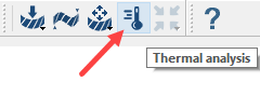
In the main window toolbar, click the (Thermal analysis) icon.
Figure 2.
The new analysis will appear in the Project Tree
as a Thermal branch.
Apply Temperature
Apply a temperature of 100 degrees to model faces.
Int the Project Tree, click the
Thermal branch to open the Analysis Workbench.
On the Analysis Workbench toolbar, select (Temperature).
In the dialog, verify the
Face radio button is selected.
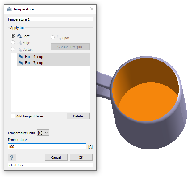
Select faces on the model from the modeling window.
Hold down the Control key.
While holding down the key, click on Face 4 (the
inner wall of the cup) and Face 7 (the inner base
of the cup).
Figure 3.
Verify that Temperature units are set to [C].
For Temperature, enter 100.
Specify Temperature Units and value.
Click OK.
The load will appear in the Thermal branch under Thermal conditions. A
representation of the load will appear on the model.
Apply Convection
Apply convection to the cup model.
In the Project Tree, click on a Thermal analysis branch to open the
Analysis Workbench.
On the workbench toolbar, click the
(Convection) icon.
In the dialog, verify the
Face radio button is selected.
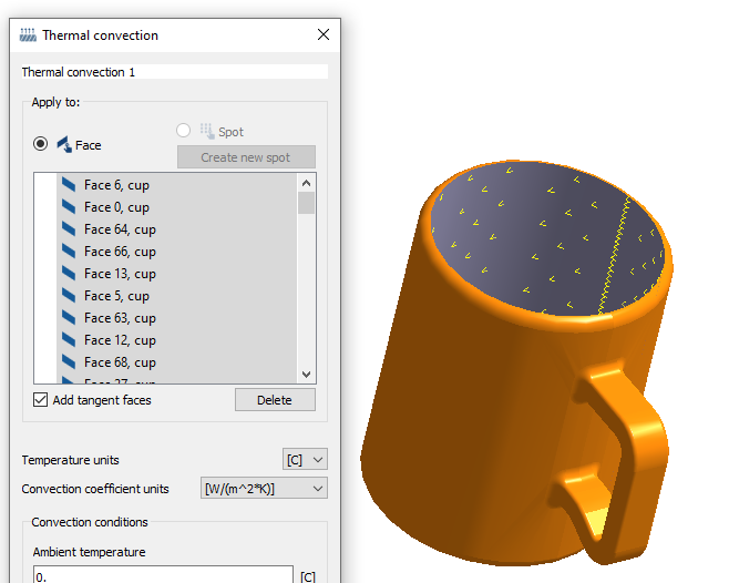
Select the outer faces of the cup.
In the dialog, activate the Add tangent faces
checkbox.
In the modeling window, select one of the cup's
outer faces.
The face will be highlighted along with all adjacent faces. Figure 4.
For Ambient temperature, enter 22.
For Convective heat transfer coefficient, 5.48e6.
Click OK.
Edit Solution Settings
Adjust solution settings.
In the Analysis branch of the Project Tree,
double-click on Solution settings: custom.
In the Solution settings dialog, for Objective select
Adapt for stiffness in the drop-down menu.
Click OK.
Run Analysis
Solve the analysis.
In the Project Tree, open
the Analysis Workbench.
Click (Solve).
Review Results
Plot the temperature contour and view minimum/maximum values.
Plot the Temperature contour.
On the Analysis workbench toolbar, click the
(Results plot) icon.
In the menu, select Temperature.
The Lengend window will appear showing the
Temperature contour plot.
In the Lengend window, select the (Show min max labels) button to view the values and
location in the modeling window.
Figure 5.
In the Bookmark browser, click
(Create bookmark).
A thumbnail will appear in the Bookmark browser. You can view the
bookmark by clicking on the thumbnail.
 (Import from file) icon.
 (Apply materials).
 to expand the Copper Alloys folder.
 (Thermal analysis) icon.
 (Temperature).
 (Convection) icon.
 (Solve).
 (Results plot) icon.
 (Show min max labels) button to view the values and
location in the modeling window.
(Show min max labels) button to view the values and
location in the modeling window.
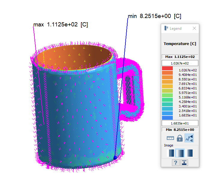 Figure 5.
  (Create bookmark).
A thumbnail will appear in the Bookmark browser. You can view the bookmark by clicking on the thumbnail.
(Create bookmark).
A thumbnail will appear in the Bookmark browser. You can view the bookmark by clicking on the thumbnail.