Pressures
A pressure is a distributed force that acts perpendicular to every point along the face. Use the Apply Pressure tool on the Loads icon to apply a pressure.
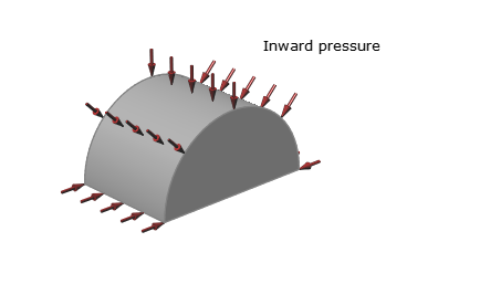
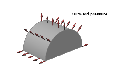
Pressures typically arise from gases or liquids pressing on a face and can act in either the inward or outward direction on a solid. To apply a distributed force to a face that acts in a single uniform direction across the entire face, use a force instead of a pressure.
Apply a Pressure
Select the Apply Pressure tool, click on a face, and enter a magnitude.
-
Click the Apply Pressure tool on the Loads icon.

-
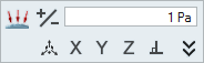
Enter the magnitude of the pressure in the text field on the microdialog and
press Enter.
-
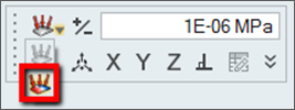
Click the
 icon to reverse the direction of the pressure.
- When created, pressures are automatically assigned to the current load case.
- You can also apply a force as a pressure if all you know is the magnitude of the force. Simply create a pressure and enter the magnitude in force units.
- Use the Property Editor to change the name, magnitude, direction, and appearance of the pressure.
Microdialog Options
Double-click a pressure to enter editing mode, which opens the Pressure microdialog.
|
|
Change the direction of the pressure. |
 |
Enter a magnitude for the pressure. The magnitude of a pressure is specified in terms of force per unit area. |
|
|
Rotate the pressure using the Move tool. |
|
|
Align the pressure to the x-, y-, or z-axis. |
|
|
Align the pressure normal (perpendicular) to the face. |
|
|
Click to orient the pressure by entering component vectors for x, y, and z. (For example, entering 1, 0, 0 would orient it in the positive x direction.) |
Pressure Mapping
Use the Pressure Mapping table to enter the position and magnitude of your pressure data. You can also import this data in .csv format
You can apply a non-uniform distributed pressure using an option in the microdialog.
Selecting the Non-Uniform Pressure option opens the Pressure Mapping table, where you can enter the position and magnitude of your pressure data. You can also import this data in .csv format.
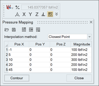
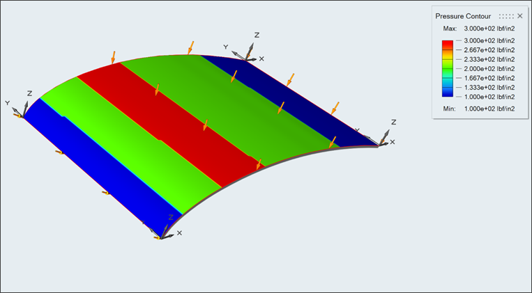
Click the Contour button on the table to visualize the contours.
Mouse Controls and Keyboard Shortcuts
| Ctrl | Apply the pressure to multiple features on the same part. |
| Right-click and mouse through the check mark to exit, or double-right-click. | Exit the tool. |