RD-T: 3030 Buckling of a
Tube Using Half Tube Mesh
This tutorial simulates buckling of a tube using half tube mesh with symmetric
boundary conditions.
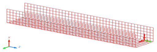
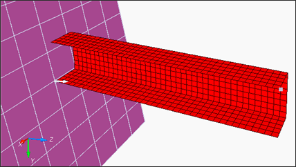
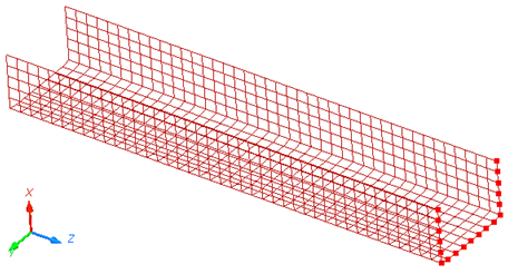
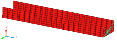
The figure illustrates the structural model used for this tutorial: a half tube with
a rectangular section (38.1 x 25.4 mm) and length of 203 mm. Figure 1. Model
The model description is as follows:
UNITS: Length (mm), Time (ms), Mass (kg), Force (kN) and Stress (GPa)
Simulation time: Engine [0 - 10 ms]
The tube thickness is 0.914 mm.
An imposed velocity of 13.3 mm/ms (~30 MPH) is applied to the right end of the
tube
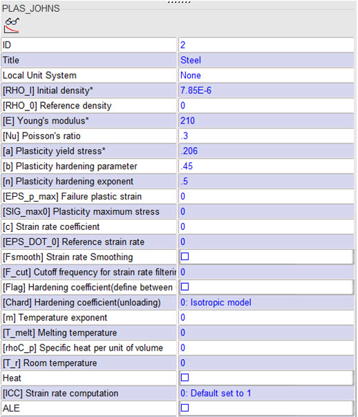
Elasto plastic material using Johnson-Cook law /MAT/PLAS_JOHNS
(STEEL).
[Rho_Initial] Initial density = 7.85e-6 Kg/mm3
[E] Young's modulus = 210 GPa
[nu] Poisson coefficient = 0.3
[a] Yield Stress = 0.206 GPa
[b] Hardening Parameter = 0.450 GPa
[n] Hardening Exponent = 0.5
File needed to complete this exercise: BOXTUBE_0000.rad
Start HyperCrash
Open HyperCrash.
Set the User profile to RadiossV2021 and the Unit system to kN mm ms.kg.
Set User Interface style as New.
Set the working directory to
<install_directory>/tutorials/hwsolvers/radioss.
Click Run.
Click File > Import > Radioss.
In the input window, select BOXTUBE_0000.rad.
Click OK.
Create and Assign a Material
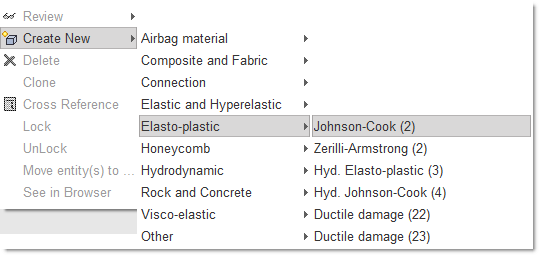
Click Model > Material.
In the window, right-click and choose Create New > Elasto-plastic > Johnson-Cook (2).
Figure 2.
For Title, enter Steel.
Enter all the material data, as shown.
Figure 3.
Right-click in the Support entry box and click
Select in graphics.
Select Include picked parts and select boxtube
in the modeling window.
Press Enter, or click Yes in the
lower right corner.
Click Save and then click
Close.
Create and Assign a Property
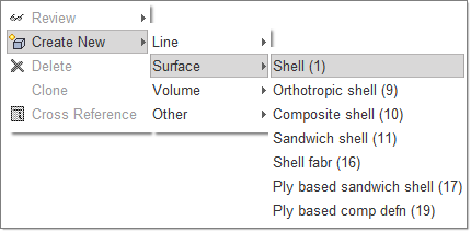
Click Model > Property.
In the window, right-click and select Create New > Surface > Shell (1).
Figure 4.
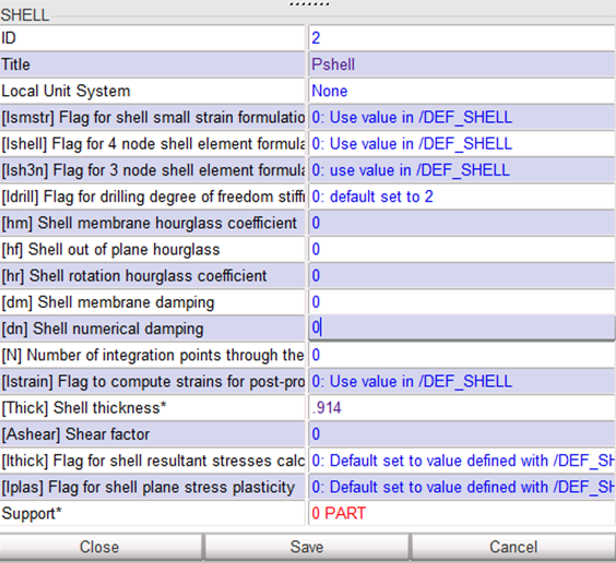
For Title, enter Pshell.
For Shell thickness, enter 0.914.
Figure 5.
Right-click in the Support entry box and click
Select in graphics.
Select Include picked parts and select boxtube
in the modeling window.
Press Enter, or click Yes in the
lower right corner.
Click Save and then click
Close.
Define the Rigid Body
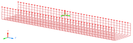
Click Mesh Editing > Rigid Body. Right-click in the display list area and select
Create New.
Right-click in the modeling window and select
Add nodes by box selection icon to select the nodes in the modeling window, as shown below:
Figure 6.
Press Enter or click Save to
validate.
Figure 7.
Note: For the remainder of the tutorial, you need to have the ID of the main
node of the rigid body.
Click Show Node Info icon in the toolbar, and select the rigid body main node
in the modeling window.
The Node ID appears in the message window (node ID: 803).
Click Cancel in the lower right corner to exit the
picking loop.
Click Close.
Define Boundary Conditions
Click LoadCase > Boundary Condition.
Right-click in the display list area and select Create
New.
In the Boundary condition field, enter the name
Rigid_BC.
In the Node by Id field, enter 803, then click
Ok.
To constrain the nodes, toggle Tx,
Ty, Rx,
Ry and Rz.
Figure 8.
Click Save.
Define Boundary Conditions Representing Symmetry
In the Boundary condition display list area, select Create
New.
Name the new constraint set symmetry.
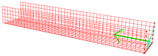
Right-click in the Support entry box and click
Select in graphics.
Select Add nodes by box selection icon to select the nodes in the modeling window, as shown below:
Figure 9.
Right-click to validate.
Toggle Tx, Ry and
Rz.
Click Save, then click
Close.
Define the Imposed Velocity
Click LoadCase > Imposed Velocity. Right-click in the display list area and select
Create New.
For Title, enter VELOCITY.
Right-click in the Time function parameter entry box and
select Define New.
A Function Window opens.
For the function name, enter FUNC_VEL.
Enter the first point (0, 13.3) and click
Validate.
Enter the second point (1e30, 13.3) and click
Validate.
Click Save in the Function Window to accept the
function.
Expand the Advanced selector at the bottom and in the
Node by Id field, enter 803 and click
Ok, (or toggle Add RB main
nodes).
Go to the Properties tab and enter a Y-Scale factor = -1.
Set the direction of the imposed velocity to Z
(translation).
Click Save and then click
Close.
Figure 10.
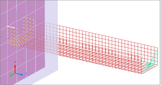
Define a Rigid Wall
Click LoadCase > Rigid Wall > Create.
For Select RWALL, select Infinite Plane.
For Title, enter RIGID WALL.
Enter the following values:
M0:
X= 0
Y= 38.1
Z= -204
M1:
X= 0
Y= 38.1
Z= 1
In the Distance to search secondary nodes field, enter
20.
Toggle See.
Click See to visualize it in the modeling window.
Figure 11.
Click Save, then click
Close.
Create a Self Contact for the Tube
Click LoadCase > Contact Interface.
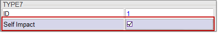
Right-click in the Contact Interface list and select Create New > Multi usage (Type 7).
Toggle Self impact.
Figure 12.
Right-click in the modeling window, and select
Include picked parts icon and select the part in the modeling window.
Click Yes in the lower right corner of the main window
to validate.
For Title, enter the name Contact.
Set Scale factor for stiffness as 1.
Set Min. gap for impact active to 0.900.
Set Coulomb friction to 0.200.
Click Save, then click
Close.
Export the Model
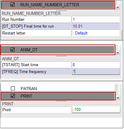
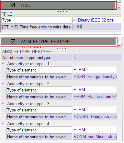
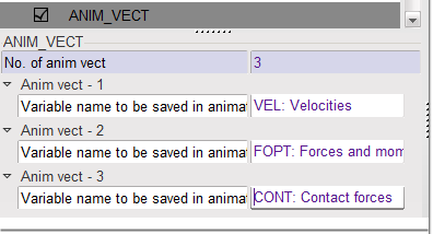
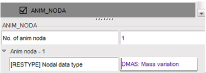
Under the Model menu, select Control Card.
Check Control Card to activate it.
Note: Make sure to save it before moving to the next Control
Card.
Figure 13. Figure 14. Figure 15. Figure 16.
Click File > Export > Radioss.
In the Write Block Format 140 Radioss File window
that opens up, enter the name as BOXTUBE and click
OK.
Leave the Header of Radioss File window empty and
click Save Model.
The Starter file BOXTUBE_0000.rad is written. The
model is now ready to run through the Starter and the Engine.
Open Compute Console from the Windows Start Menu
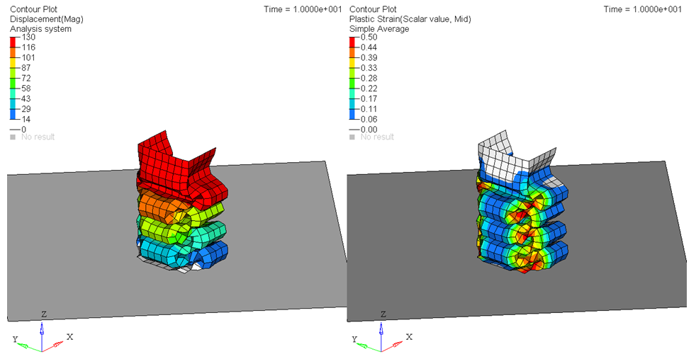
Review the Results
Using HyperView, plot the displacement and strain
contour at 10 ms.
 and select boxtube
in the modeling window.
and select boxtube
in the modeling window.
 to select the nodes in the modeling window, as shown below:
 in the toolbar, and select the rigid body main node
in the modeling window.
The Node ID appears in the message window (node ID: 803).
in the toolbar, and select the rigid body main node
in the modeling window.
The Node ID appears in the message window (node ID: 803).