Single Input File Format
Model Setup
A multiple input format setup was first introduced in Radioss Multi-Domain technique. The main drawback of this setup is that it implies a lot of work for the user who has to manually build several independent input files. It can be very long, difficult and the source of mistakes in the case of small domains extracted from very large and complex models.
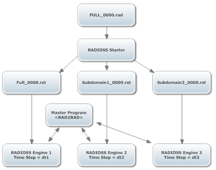
Figure 1. Subdomain Setup Architecture
Currently, only one domain can be specified, but this limitation can be extended in the future.
Automatic Creation of Subdomain
The subdomain is simply defined by a list of parts.
Split Model
The first step of the creation of a subdomain is the splitting of the full model. This is achieved by launching one Starter child process per domain. Each process only keeps the part associated to it and the corresponding nodes and elements. Entity groups, such as /GRNOD, /GRPART or /SURF are split as well, allowing a split of a lot of options (if an option refers to nothing in one domain it is suppressed). Some options are more complex to split and need a specific treatment which often implies a modification of the domain definition. Some other options can not be split. For more information about options incompatible with Multi-Domains, refer to Current Limitations.
As a result, a subdomain is most of the time composed of the parts specified by the user (with their related nodes and elements) and also by some other elements or nodes that are automatically added because of the split of some options.
Connections between Domains
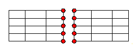
Figure 2.
Contact between Domains
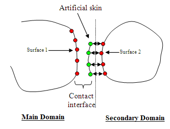
Figure 3.
With the single input file setup the contacts between domains are always computed in the subdomain mainly because the quality of the coupling is far better when the contact is treated in the domain with the smallest time step.
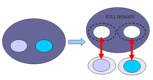
Figure 4.
- /INTER/TYPE5
- /INTER/TYPE7
- /INTER/TYPE10
- /INTER/TYPE11
- /INTER/TYPE18
- /INTER/TYPE24, if (surf_ID1 > 0, surf_ID2 > 0) or (surf_ID1 > 0, surf_ID2 = 0). Not if (grnd_IDs > 0, surf_ID1= 0, surf_ID2 > 0).
User-defined Connections between Domains
- Rigid bodies: in the case of rigid bodies that connecting two domains, a specific treatment is applied. The rigid body is split in two, and a computation of mass, inertia matrix and position of the center of gravity is performed for each domain. Then, the two mai nodes of the two parts of the rigid body are coupled by RAD2RAD using a formulation similar to the one used for classical node-to-node coupling but adapted to non-spherical inertia.
- Tied interface: in the case of a tied interface TYPE2 with main elements on one domain and secondary nodes the other one, a different strategy is used. This strategy is similar to what is done for the contacts. The main elements are duplicated with void material in the domain containing the secondary nodes in order to have the tied interface fully defined in this domain. Then, the Multi-Domain coupling is only applied on the nodes of the main elements. If both domains contain secondary nodes, the duplication of main elements is performed on both sides.
- Rigid Links, RBE3 and Cylindrical Joints: the same idea is applied to rigid link and RBE3. If one of these options has secondary nodes on two domains, all the missing secondary nodes are duplicated on both sides and all the secondary nodes are coupled by the RAD2RAD. The option is then computed on both sides.
- /MPC
- /RBE2
- /GJOINT
Data Input
Starter Input File
/SUBDOMAIN/subdomain_ID
subdomain_title
Part1 Part2 ... Partn- Partn
- Identifier of the parts that belong to the subdomain
- subdomain_ID
- Domain identifier
- subdomain_title
- Subdomain name (that will be the rootname of one Engine file)
Engine Input File
/RAD2RAD/ONOne Engine file name comes from the Starter input file rootname: "full_model_rootname"_0001.rad and the other Engine input file name relating to the subdomain comes from the subdomain_title: subdomain_title_0001.rad given to the /SUBDOMAIN card in the Starter input file.
RAD2RAD Input File
Data Output
Starter Output Files
Separate Starter output files are generated for each domain.
Time History Files
A single Time History file is generated containing all information from both domains. This file has the same rootname as the Starter input file. This file content is equivalent to what is obtained following a classical monodomain computation.
All parameters for Time History output (type of time history, output frequency, format, and so on) must be specified in the Engine file of the main domain. If the parameters for time history are defined in the sub-domain Engine input file, they will be ignored.
As the frequency for the printout of the TH file is defined by the main domain, the minimum time interval allowed between two prints of a TH file is the time step of the main domain. For better accuracy, it is recommended to use a time frequency that is much higher than the time step of the main domain.
ABF Files
One ABF file is generated by each Radioss Engine. Therefore, to plot the whole model global variables, each domain's global variable of must be added up.
Output File
Global variables of the whole model can be computed by simply summing up the global variables printed in the output file of each domain (each Engine output).
- Energy error: The energy balance is computed in each domain independently from the other domain. It means that for each domain, the Multi-Domain coupling forces are considered as external forces and their work is added to the work of the external forces. This work is only used internally for the energy balance computation. It is not included in the value of the work of the external forces printed in the output file or in the time history.
- Mass change: The mass change is also computed locally, meaning that it is the ratio of the added mass in the selected domain over the mass of this domain.
Animation Files
A set of animation files is generated by each Engine. With HyperView it is possible to visualize the two domains simultaneously by simply making an overlay.
RAD2RAD Output File
The output file rad2rad.out is generated by the RAD2RAD executable. This file contains useful information about the connections between domains (number of common nodes, type of coupling, and so on).
SPEEDUP Estimation
As of version 14.0, an estimation of the speedup is computed in the Starter in order to determine the potential efficiency of the multi-domains method. The value is printed in the Starter output file of the main domain. So, if during the computation the time steps change drastically in one domain, the speedup estimation will be irrelevant.
Time step control options defined in the Engine input file (/DT/NODA/CST, /DTIX, ...) accounted for in the time step estimations in the Starter.
CPU Allocation
The Radioss domains are treated sequentially, which means that only one Radioss process is run at a time. The total CPU resource is automatically allocated to the running process and the others are put in a no CPU consuming waiting mode. With the subdomain setup, the same number of SPMD domains is automatically allocated to all domains. For better performances, the same number of SMP threads per SPMD domain should be used for each domain when running in Hybrid-MPP.
As of version 12.0.210, the RAD2RAD executable is fully parallelized. It means that RAD2RAD must
be launched exactly like the Engine executables (same mpi options)
and that the same number of SPMD domains must be used for both Engine and RAD2RAD
processes.
Launch a Multi-Domain Analysis
There are two ways to launch a Multi-Domain computation: manually and through a script.
An easier way to launch a Multi-Domain computation is to use a script.
Current Limitations
Only one subdomain can be defined (it will be possible to define several subdomains in a future release).
- /FX_BODY
- /GJOINT
- /MPC
- /RBE2
Multi-Domain is incompatible with all kinematic conditions based on Lagrange multipliers, due to incompatibility with the coupling formulation.
Multi-Domain is not yet compatible with AMS (Advanced Mass Scaling), Rayleigh Damping (/DAMP), Dynamic Relaxation (/DYREL), unless nodes are not part of the cross-domain interface or contact, interfaces TYPE1.
The sensors of type GAUGE, INTER and RWAL are not yet synchronized between domains. Meaning that if a sensor and all its associated features are not confined in one domain, the behavior of this sensor may be incorrect. Nevertheless, sensors of type DIST, ACCE and TIME are fully compatible with Multi-Domain and synchronized between domains.