Multiple Input File Format
Model Setup
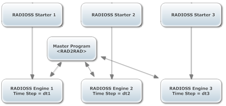
Figure 1.
Connection between Domains
A connection (or link) between 2 domains is always defined by 2 groups of nodes relating to the two corresponding meshes to be connected to each other and the type of this connection. Below is a list of available types of connections in RAD2RAD.
TYPE 1: Shell to Shell (Schur Dual Method)
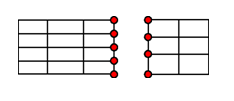
Figure 2.
TYPE 2: Shell to Beam (Schur Dual Method)
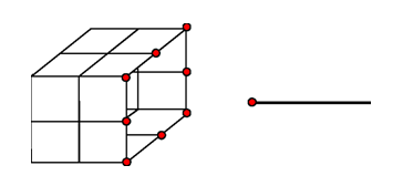
Figure 3.
TYPE 4: Node to Node (Schur Primal Method)
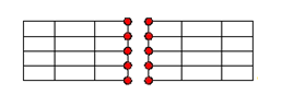
Figure 4.
This method is strictly equivalent to TYPE 1 for compatible meshes; but consumes less CPU time, as no matrix assembly and no inversion have to be performed. Furthermore, in this case, since only nodal data is needed, it can be used to connect any type of nodes (attached to any type of elements).
Contact between Domains
TYPE 5: Connection
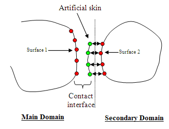
Figure 5.
/LINK/TYPE5
Main_Domain Link_Id1
Second_Domain Link_Id2- /INTER/TYPE5
- /INTER/TYPE7
- /INTER/TYPE10
- /INTER/TYPE11
- /INTER/TYPE18
- /INTER/TYPE24, if (surf_ID11 > 0, surf_ID2 > 0) or (surf_ID1 > 0, surf_ID2 = 0). Not if (grnd_IDs > 0, surf_ID1 = 0, surf_ID2 > 0).
Mass and nodal stiffness are transferred by RAD2RAD connection TYPE5 from the secondary domain to the artificial skin. Therefore, modifications of mass and nodal time step may be observed in the main domain at the beginning of the computation.
/LINK/TYPE5
Main_Domain Link_Id1
Second_Domain Link_Id2- A rigid body duplication, the main node must be specified in the RAD2RAD connection TYPE5.
- Interface TYPE2 duplication, an additional flag /TIED must be specified in the RAD2RAD input file.
The RAD2RAD is incompatible with Lagrange multipliers kinematic conditions, such as interface /INTER/LAGMUL/TYPE2 and /RWALL/LAGMUL.
Data Input
Starter Input File
/EXTERN/LINK/Link_ID
title
gr_ID- gr_ID
- Nodal group identifier defining frontier nodes with other domain(s)
- Link_ID
- Link identifier
The number of external links in a Radioss model is not limited. The only restriction is that different links should not contain common nodes. Each link defines a distinct interface between current model and the external world.
Engine Input File
/RAD2RAD/ONCPU Allocation
The Radioss domains are treated alternately; which means that only one Radioss process is running at a time. The full CPU resource is automatically allocated by the RAD2RAD to the running Engine process and the other processes are put in a no CPU consuming waiting mode. It means that all the same available CPU resources must be allocated to each domain during its computation.
Launch a Multi-Domain Analysis
There are two ways to launch a Multi-Domain computation, manually and through a script.
An easier way to launch a Multi-Domain computation is to use a script.
RAD2RAD Parallelization
-nt in the command line like for the
Engines or directly in the RAD2RAD input file using the keyword
/PROC/nthread.MPI Settings
- HP-MPI: MPI_FLAGS set to y0
- Open-MPI: OMPI_MCA_mpi_yield_when_idle set to 1
- Intel-MPI: Default settings can be used
Output Files
- Radioss: Separate output files are generated by each Radioss process.
- RAD2RAD: A specific output file named rad2rad.out is generated by RAD2RAD.
Version Restrictions
- Each sub-domain is constructed as a complete. Separate Radioss model, using its own complete input files.
- The data transfers between Radioss processes and main program use the pipe system method of communication. All Radioss Engines and the RAD2RAD must be started on the same hardware node.
- Kinematic conditions on common nodes between domains are compatible only with connection TYPE5.
- The RAD2RAD program is not parallelized for multiple input files setup. This may lead to reduced performance in Multi-Domain computations with large subdomains running on a large number of CPU's.
- Currently, the Multi-Domain calculus is not automatically executed by the main program. All Radioss Starters must have been executed before the RAD2RAD program is launched. Although, batch execution is possible, RAD2RAD and all Radioss Engine processes must be launched independently and in parallel, on the single hardware node.
- For each Radioss domain, the number of links is limited to 15 and the number of CPU's is limited to 128.
Example: RAD2RAD Input File
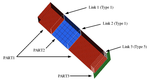
Figure 6. Model
RAD2RAD Input File
$===============================================================
$ RAD2RAD R8 INPUT FILE :
$===============================================================
$ 1. PARTS DEFINITION
$===============================================================
/DOMAIN/PART1
1 2 3
/DOMAIN/PART2
4 5
/DOMAIN/PART3
9
$===============================================================
$ 2. INTERFACES  DEFINITION
$===============================================================
/LINK/TYPE1
PART1 2
PART2 5
/LINK/TYPE1
PART1 1PART2 4
/LINK/TYPE5
PART3 9
PART1 3
$===============================================================
$3 OPTIONS
$===============================================================
/MLTPS/ON
0.1 0.1
/MESHL/MORFIN
/RADIUS/1e-7
/END   $===============================================================