Domain Parameters

In the domain section the global definitions for the simulation are set, such as the number of dimensions and the numerical reference parameters.

domain
{
     ndim                              3
     min_domain                        "0.0 0.0 0.0"
     max_domain                        "1.0 3.0 0.0"
     BC_min                            "OUTLET PERIODIC SIMPLEOUTLET"
     BC_max                            "OUTLET PERIODIC SIMPLEOUTLET"

     outlet_vel                        "0.05 0.0 0.0" 
     outlet_bodyforce_on               true

     ref_rho                           1000.
     ref_length                        0.1
     ref_vel                           1.0
     ref_curv                          1.0
     ref_visc                          1.0

     bodyforce                         "0. 0. 0."
     t_damp_bodyforce_start            0.
     t_damp_bodyforce_end              0.
     bodyforcefile                     inputFileName.txt 
		
     inputfile                         initialparticlepositions.txt
     inputfileReadMode                 AUTO                         
     inputfile_factor                  0.001
}
ndim
The dimensionality of the problem
Options: 1, 2, 3
If both min_domain and max_domain are not specified in the configuration file, the code will automatically detect the minimum and maximum dimensions of the case and create a bounding box automatically. This is convenient if the user is operating with a closed geometry, such as a gearbox. If the user would like to simulate a sloshing/splashing case where the fluid is not constrained within solid walls, or if there are periodic or inlet boundary conditions associated with the domain, it is necessary to manually prescribe the size of the domain (bounding box).
min_domain
Minimum bounds of the computational box (vector defining a point location)
If both min_domain and max_domain are not specified in the configuration file, the variables will be determined by the code automatically (please read the paragraph above for clarification).
max_domain
Maximum bounds of the computational box (vector defining a point location)
If both min_domain and max_domain are not specified in the configuration file, the variables will be determined by the code automatically (please read the paragraph above for clarification).
Similar to the min_domain and max_domain commands, you can also completely leave out the definitions of the boundary conditions, under the assumption that you are fine with the default option which is SIMPLEOUTLET.
BC_min (Domain parameters)
Boundary condition at the minimum boundary
Options: OPEN / PERIODIC / OUTLET / SIMPLEOUTLET
Default: SIMPLEOUTLET
The SIMPLEOUTLET boundary simply deletes all the particles that cross it.
OUTLET boundary is different from a SIMPLEOUTLET in that, by default, it has an associated zero-gradient velocity condition. Alternatively, with OUTLET you can specify the outlet velocity (outlet_vel) and add the influence of the gravitational force on the outgoing fluid (outlet_bodyforce_on). There can be multiple OUTLET boundaries specified in the domain.
Related options: outlet_vel, outlet_bodyforce_on.
Note: Do not use the keyword INLET here. For more information, see Inlet Definitions.
BC_max (Domain parameters)
Boundary condition at the minimum boundary
Options: OPEN / PERIODIC / OUTLET / SIMPLEOUTLET
Default: SIMPLEOUTLET
The SIMPLEOUTLET boundary simply deletes all the particles that cross it.
OUTLET boundary is different from a SIMPLEOUTLET in that, by default, it has an associated zero-gradient velocity condition. Alternatively, with OUTLET you can specify the outlet velocity (outlet_vel) and add the influence of the gravitational force on the outgoing fluid (outlet_bodyforce_on). There can be multiple OUTLET boundaries specified in the domain.
Related options: outlet_vel, outlet_bodyforce_on.
Note: Do not use the keyword INLET here. For more information, see Inlet Definitions.

To better illustrate the nature of the nanoFluidX BC_min and BC_max boundaries, see Figure 1.


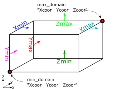
Figure 1. . Sketch of the nanoFluidX Domain Boundaries. Each of the six bounding planes is marked in a separate color, with the colored arrow showing the surface normal of the boundary. The direction of these surface normals in the sketch has no influence on the code execution, they are provided to help visualize the domain. The two red dots at the opposite corners of the domain are minimum and maximum extent of the domain.
Note: Starting with version 2.03, since it is possible to define multiple inlets in a single domain nanoFluidX has a separate parameter section for the inlet definitions. For more information, see Inlet Definitions.
outlet_vel
Specifies the velocity of the OUTLET boundary
If left out, the OUTLET will automatically apply zero-gradient velocity at the boundary.
If there are multiple outlets, all of them will use the same outlet velocity value.
outlet_bodyforce_on
If this flag is switched on, the outlet particles will experience the prescribed body force. This is useful in cases where the outlet plane is perpendicular to the body force (gravity) direction, in which case the zero gradient velocity at the outlet no longer applies.
Default: false

Reference values have been automated as well. You can still choose to set them manually (as is recommended), but otherwise, depending on the case definition, the code will automatically pick up the reference values, provided that max_dist commaned is defined in the motion definition.

For density, the lowest fluid density will be picked up as the reference. For length, the code will analyze the size of the domain in the direction of the body force applied and choose that length as the reference length. Of course, this means that if the user is using variable body force – the reference length is specified manually.

For velocity, if there is defined motion in the configuration file, the code will automatically calculate maximal velocity of the motion, multiply it by a ref_vel_factor (the default value is 1.5) for conservative purposes and set that value as the reference velocity. Of course, if there is no motion defined or if the motion is rigid body or position file – the user still has to define the reference velocity manually. For reference curvature, the default curvature will be set as 1/(5*dx), as we believe that in order to resolve droplets accurately you need to have a droplet radius of at least 5 particles.

ref_rho
Reference density
Should be the lowest fluid density in the domain
Default: If not specified, the code will automatically detect it.
ref_length
Reference length: A typical length scale defining the relevant physics.
Examples:
  • Diameter in case of a channel flow
  • Fluid height (depth) for hydrostatic problems (e.g. gearboxes, tanks etc.)
Default: The code will automatically try to find a relevant length for a hydrostatic problem.
It is recommended however that the user specifies this reference value, as it can be difficult for the code to identify the correct value in certain cases.
ref_vel
Reference velocity
Should be highest expected velocity in the domain
Default: If the motion is defined in the .cfg file, the code will automatically calculate the maximum velocity and multiply it by the ref_vel_factor value in order to assure stable running of the simulation.
ref_curv
Reference curvature (needed only if surften_model is set to ADAMI or SINGLE_PHASE)
Should be the curvature of the smallest droplet that needs to be resolved (1/radius of the droplet)
Default: If not specified, the value will be set to 1/(5*dx)
Related options/commands: surften_model
ref_visc
Reference viscosity (needed only if viscTempCoupling is set to true).
Should be the highest expected viscosity in the domain
Related options/commands: viscTempCoupling, Viscosity-temperature dependence models
bodyforce
Gravitational acceleration
Body force vector must be specified (if using variable body force file, the latter bodyforcefile command will overwrite it).
t_damp_bodyforce_start
Before this time the body force is zero. Starting from this time a gravitational acceleration is added to the system.
Note: Ramping up to the given value is defined with t_damp_bodyforce_start and t_damp_bodyforce_end commands.
Defaults: 0
t_damp_bodyforce_end
This time must not be smaller than t_damp_bodyforce_start. Within the time interval between t_damp_bodyforce_start and t_damp_bodyforce_end the gravitational acceleration is ramped up to reach the full body force at t_damp_bodyforce_end. At later times the full body force is applied.
Defaults: 0
bodyforcefile
Name of the file that contains the body force vector as a function of time, allowing simulations of sloshing tanks.
This is simultaneously a switch for the code. If you have this command present, it will use the specified input file and ignore the previous bodyforce input.
Related options/commands: Varying body force (acceleration)
inputfile
This file is the geometry input file (textfile) and needs to be present in the folder where the simulation is launched together with the config-file.
inputfile_factor
This factor can be used to scale the input file content.
Note: nanoFluidX uses SI-units. Therefore, this factor is useful if a model is created in SimLab in millimeter-units and needs to be converted to meters while reading in.
Example:
  • Model in mm → convert to meters: 0.001
  • Model in km → convert to meters: 1000
Default: 1.0
inputfileReadMode
Describes the data format that is to be read in
Options: INPTFL_AUTO, INPTFL_PXYZ, INPTFL_PXYZUVW
  • INPTFL_AUTO reads all of the lines that are provided in the file.
  • INPTFL_PXYZ reads 4 columns: Phase ID, x, y and z coordinates.
  • INPTFL_PXYZUVW reads 7 columns: Phase ID, x, y and z coordinates and u, v and w components of the initial velocity.
Default: INPTFL_AUTO