Inlet Definitions
Since version 2.03, nanoFluidX has a separate inlets parameter section which allows to define multiple inlets in a single domain, inserting if desired multiple different fluid phases.
inlets
{
    inlet
    {
        inlet_type                 RECTANGULAR
        min_inlet_domain           "-0.02 -0.001 -0.02"
        max_inlet_domain           "0.02 0.001 0.02"
        inlet_phase                1
        inlet_vel                  "0.0 -0.05 0.0"
        t_damp_inletvel_start      0.0
        t_damp_inletvel_end        0.0
        surrounding_ghost_cells    true
        BC_max		        "OUTLET INLET  OUTLET"
        BC_min		        "OUTLET OUTLET OUTLET"
    }
    inlet
    {
        inlet_type                 CIRCULAR
        inlet_center               "-0.02 -0.001 -0.02"
        inlet_radius               0.02
        inlet_phase                1
        inlet_vel                  "0.0 -0.05 0.0"
        t_damp_inletvel_start      0.0
        t_damp_inletvel_end        0.0
        surrounding_ghost_cells    true
        BC_max		        "OUTLET INLET  OUTLET"
        BC_min		        "OUTLET OUTLET OUTLET"
    }
}
Starting with v2019, nanoFluidX also has an option to specify circular inlets and starting with 2021, the user can define arbitrary shape and orientation inlets using the INLET REGION feature.
By specifying an inlet boundary, we define a rectangle at one of the min/max domain boundaries through which a fluid enters at a specified velocity. As already mentioned, it is now possible to define an arbitrary number of inlets on any of the BC_min/BC_max planes. We define multiple inlets by creating multiple “inlet” sub-sections in the main “inlets” parameter section. Each inlet is geometrically defined by two points which belong to one of the BC_min/BC_max planes: min_inlet_domain and max_inlet_domain.
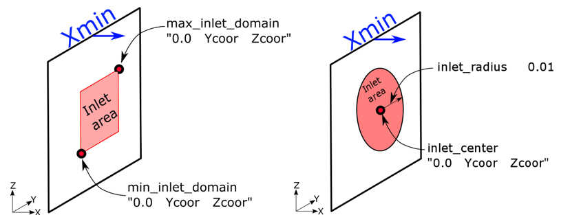
Figure 1. . Definition of an inlet area in the Xmin plane. RECTANGULAR: The two red dots are points which bound the inlet area on the Xmin plane. CIRCULAR: Defining location of the inlet center and its radius unambiguously defines a circular inlet in the Xmin plane. Please note that specifying the X-coordinate of the points is meaningless for this plane, as the plane has already been defined.
- inlet_type
- Inlet type.
- min_inlet_domain
- Specifies the starting (minimum) point of the inlet rectangle.
- max_inlet_domain
- Specifies the ending (maximum) point of the inlet rectangle.
- inlet_center
- Specifies the center of the circular inlet.
- inlet_radius
- Scalar value defining the radius of the circular inlet.
- inlet_phase
- Specify the number of the phase that comes through the inlet.
- inlet_vel
- Prescribed inlet velocity.Note: Inlet velocities can be only perpendicular to the specified boundary plane.
- t_damp_inletvel_start
- Begin time for the inlet velocity damping.
- t_damp_inletvel_end
- End time of the damping for the inlet velocity.
- surrounding_ghost_cells
- Creates a layer of ghost particles surrounding the inlet. This is to help potential leaks around the inlet zone, as the additional layer of ghost particles will equalize the pressure of the particles trying to escape through the corners between the geometry and the inlet boundary plane.
- BC_min (Inlet parameters)
- This definition of BC_min serves the sole purpose of defining to which boundary plane does the inlet belong to. All the other possible boundary condition keywords (OPEN / PERIODIC / OUTLET / SIMPLEOUTLET) will be ignored.
- BC_max (Inlet parameters)
- This definition of BC_min serves the sole purpose of defining to which boundary plane does the inlet belong to. All the other possible boundary condition keywords (OPEN / PERIODIC / OUTLET / SIMPLEOUTLET) will be ignored.
We understand that this can introduce some confusion into the process, but for practical reasons, and due to the current text-based input, the definition of multiple inlets could not be carried out in a different manner. This implementation of inlets is still active for historical reasons, but is subject to deprecation if the user community adopts the INLET_REGIONS.