Laminar Flow Through a Channel with Heated Walls

In this application, AcuSolve is used to simulate high Peclet number laminar flow through a channel with heated walls. AcuSolve results are compared with analytical results adapted from Hua and Pillai (2010). The close agreement of AcuSolve results with analytical results validates the ability of AcuSolve to model cases involving heat transfer to a moving fluid with a high Peclet number.

Problem Description

The problem consists of water at 20 °C flowing through a channel of infinite width with top and bottom walls heated to 75 °C. The channel is 0.2 m high and 0.8 m long, as shown in the following image, which is not drawn to scale. A centrally located slice 0.02 m wide is modeled with slip boundary conditions so that side-wall influences can be ignored. Water enters the channel with an average velocity of 0.003 m/s. As the fluid flows through the channel, it is heated by the top and bottom plates.


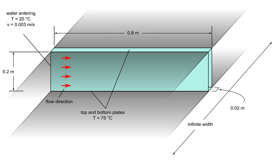
Figure 1. Critical Dimensions and Parameters for Simulating Laminar Flow Through a Channel with Heated Walls
The simulation was performed as a two dimensional problem by restricting flow in the out-of-plane direction through the use of a mesh that is one element thick. In addition, the symmetry of the geometry in the height direction is exploited to allow for modeling only half of the geometry. These characteristics allow for accurate simulation of flow while minimizing computational time.


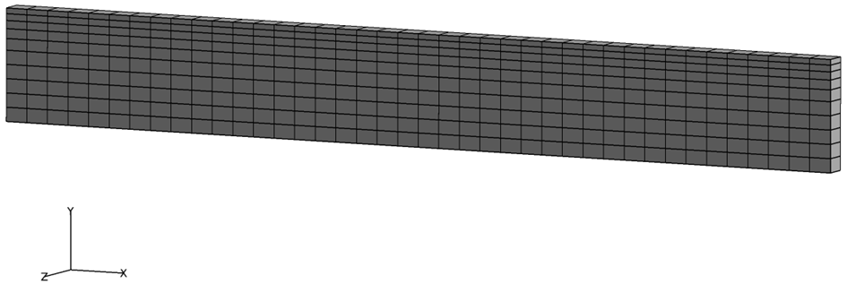
Figure 2. Mesh (Top Half of the Channel) used for Simulating Laminar Flow Through a Channel with Heated Walls

AcuSolve Results

The AcuSolve solution converged to a steady state and the results reflect the mean flow conditions. As the cool water enters the channel at temperature less than that of the walls, heat is transferred to the water by conduction. As the fluid travels along the channel, the temperature differential between the wall and the adjacent water decreases. The thermal boundary layer within the water develops as the flow propagates downstream.


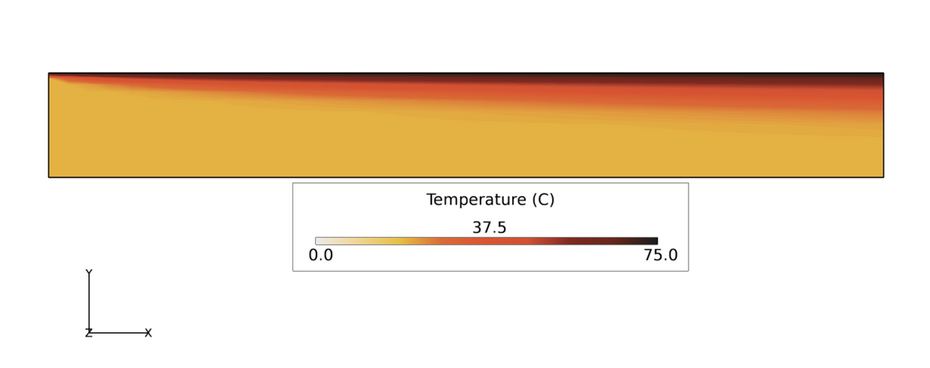
Figure 3. Temperature Contours Along the Top Half of a Heated Channel
Temperature at a specified vertical position in the channel increases along the length of the channel. The nature of that temperature change is dependent on proximity to the heated wall. Water in the center of the flow will have the least temperature change. Since this problem was solved for symmetrical flow, only the top half of the flow region was modeled. The vertical position for results shown in the following figure are based on the center of flow having a Y-position of 0. For a vertical position near the center of flow (Y=0.0595) there is minimal change in temperature.


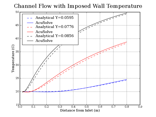
Figure 4. Temperature Plotted Against Distance from Inlet for 3 Different Heights from the Channel Center Line

Summary

The AcuSolve results compare well with the analytical results for the development of a thermal boundary layer in a heated channel. In this application, the model is set up to yield large gradients as the flow convects away from the inlet. The boundary conditions and mesh size were chosen specifically to yield a high Peclet number. The element Peclet number in the flow direction in this case is Pe=30.0, as calculated from the following equation.

(1)
Pe= ρCp| v |he k MathType@MTEF@5@5@+= feaagKart1ev2aaatCvAUfeBSjuyZL2yd9gzLbvyNv2CaerbuLwBLn hiov2DGi1BTfMBaeXatLxBI9gBaerbd9wDYLwzYbItLDharqqtubsr 4rNCHbGeaGqiVu0Je9sqqrpepC0xbbL8F4rqqrFfpeea0xe9Lq=Jc9 vqaqpepm0xbba9pwe9Q8fs0=yqaqpepae9pg0FirpepeKkFr0xfr=x fr=xb9adbaqaaeGaciGaaiaabeqaamaabaabaaGcbaGaamiuaSGaam yzaiabg2da9OWaaSaaaeaacqaHbpGCcaWGdbadcaWGWbGcdaabdaqa aiaadAhaaiaawEa7caGLiWoacaWGObWccaWGLbaakeaacaWGRbaaaa aa@436C@

where ρ MathType@MTEF@5@5@+= feaagKart1ev2aaatCvAUfeBSjuyZL2yd9gzLbvyNv2CaerbuLwBLn hiov2DGi1BTfMBaeXatLxBI9gBaerbd9wDYLwzYbItLDharqqtubsr 4rNCHbGeaGqiVu0Je9sqqrpepC0xbbL8F4rqqrFfpeea0xe9Lq=Jc9 vqaqpepm0xbba9pwe9Q8fs0=yqaqpepae9pg0FirpepeKkFr0xfr=x fr=xb9adbaqaaeGaciGaaiaabeqaamaabaabaaGcbaGaeqyWdihaaa@37B6@ is the density, C P MathType@MTEF@5@5@+= feaagKart1ev2aaatCvAUfeBSjuyZL2yd9gzLbvyNv2CaerbuLwBLn hiov2DGi1BTfMBaeXatLxBI9gBaerbd9wDYLwzYbItLDharqqtubsr 4rNCHbGeaGqiVu0Je9sqqrpepC0xbbL8F4rqqrFfpeea0xe9Lq=Jc9 vqaqpepm0xbba9pwe9Q8fs0=yqaqpepae9pg0FirpepeKkFr0xfr=x fr=xb9adbaqaaeGaciGaaiaabeqaamaabaabaaGcbaGaam4qaWGaam iuaaaa@379F@ the heat capacity, ν the velocity, h e MathType@MTEF@5@5@+= feaagKart1ev2aaatCvAUfeBSjuyZL2yd9gzLbvyNv2CaerbuLwBLn hiov2DGi1BTfMBaeXatLxBI9gBaerbd9wDYLwzYbItLDharqqtubsr 4rNCHbGeaGqiVu0Je9sqqrpepC0xbbL8F4rqqrFfpeea0xe9Lq=Jc9 vqaqpepm0xbba9pwe9Q8fs0=yqaqpepae9pg0FirpepeKkFr0xfr=x fr=xb9adbaqaaeGaciGaaiaabeqaamaabaabaaGcbaGaamiAaSGaam yzaaaa@37D8@ the length, and k the thermal conductivity.

This example shows the robustness of the stabilized technique in AcuSolve when element Peclet number is high. Note that standard Galerkin finite element formulations become unstable when the element Peclet number is greater than 1.0.

Simulation Settings for Laminar Flow Through a Channel with Heated Walls

AcuConsole database file: <your working directory>\channel_laminar_heat\channel_laminar_heat.acs

Global

  • Problem Description
    • Analysis type - Steady State
    • Temperature equation - Advective Diffusive
    • Turbulence equation - Laminar
  • Auto Solution Strategy
    • Relaxation factor - 0.4
  • Material Model
    • Fluid_Material
      • Density - 1000.0 kg/m3
      • Specific Heat - 1000 J/kg-K
      • Viscosity - 1.0e-12 kg/m-sec
      • Conductivitiy - 1.0 W/m-K

    Model

  • Volumes
    • Fluid
      • Element Set
        • Material model - Fluid_Material
  • Surfaces
    • Inlet
      • Simple Boundary Condition
        • Type - Inflow
        • Inflow type - Velocity
        • X velocity - 0.003 m/sec
        • Temperature - 20 °C
    • Outlet
      • Simple Boundary Condition
        • Type - Outflow
    • Symm_MaxZ
      • Simple Boundary Condition
        • Type - Slip
    • Symm_MinY
      • Simple Boundary Condition
        • Type - Slip
    • Symm_MinZ
      • Simple Boundary Condition
        • Type - Slip
    • Wall
      • Simple Boundary Condition
        • Type - Wall
        • Temperature BC type - Value
        • Temperature - 75 °C

References

Hua Tan and K. M. Pillai. "Numerical Simulation of Reactive Flow in Liquid Composite Molding Using Flux-Corrected Transport (FCT) Based Finite Element/Control Volume (FE/CV) Method". International Journal of Heat and Mass Transfer. 53:2256-2271, 2010.