Front SLA (1pc LCA)
The Short-Long Arm (SLA) suspension is also known as a Double Wishbone suspension. The SLA name is derived from the length of the control arms. The lower arm is typically long to provide a good spring lever ratio. The upper arm is typically short to provide the proper camber curve. This suspension is widely used on cars, light trucks, and on independent suspension heavy trucks.
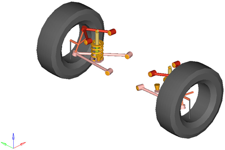
Figure 1. Front SLA Suspension with One (1) Piece Lower Control Arm and Optional Subsystems: Coil Spring, Shock Absorber, and External Jounce Bumper Subsystems
Model Use
- The wheel body represents the mass and inertia of the tire and the rim.
- The wheel hub body represents the mass and inertia of other rotating bodies such as a brake rotor, but not the half-shafts if the suspension is driven. The wheel hub and brake rotor have no associated graphics.
- The wheel and wheel hub parts use the Wheel CG location as the center of gravity.
- Each body’s Center of Gravity (CG) is estimated from the body’s geometry. The formulas are coded into the point panel and can be seen via the graphical user interface. If more accurate CG locations are available they should be used.
- The upper control arm bushings are defined so their axes are parallel. If the front bushing is moved, both the front and rear bushing realign so that they have the same axis of rotation. The lower control arm bushing’s rotational axes are defined in the same manner.
- When the suspension is switched from Compliant to Kinematic, the upper control arm bushings are replaced with a single revolute joint located at the forward bushing, with a rotational axis directed along the line from the forward bushing to the rear-ward bushing. The lower control arm bushings are replaced with a revolute joint in the same fashion.
- Each body’s Center of Gravity (CG) is estimated from the body’s geometry. The formulas are coded into the point panel and can be seen via the graphical user interface. If more accurate CG locations are available they should be used.
- The point giving the location of the ball joint between the suspension knuckle and steering tie rod point resides in the steering system.
- A wide variety of combinations of suspensions and subsystems can be built using the
Assembly Wizard. You are encouraged to build systems and
understand the resulting model using the graphical user interface.
When building a new suspension model, build the model with all of the optional systems (stabilizer bar, etc) included in the model. Immediately turn off the systems using the Project Browser and run an analysis on the base suspension to ensure it solves properly. As data becomes available for the optional systems; activate those systems and populate them with data.
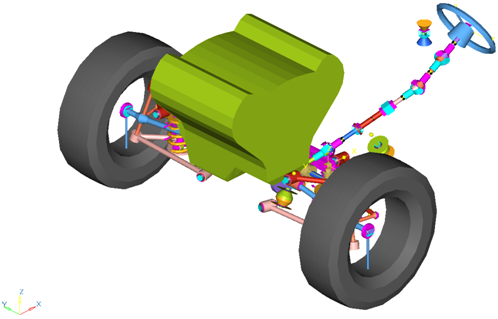
Figure 2. Front-Half-Vehicle Model Employing a SLA Suspension with One (1) Piece Lower Control Arm
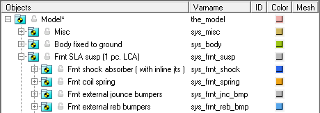
Figure 3. Browser View of a Front-Half-Vehicle Model Systems and Subsystems Employing a SLA Suspension with One (1) Piece Lower Control Arm
Points
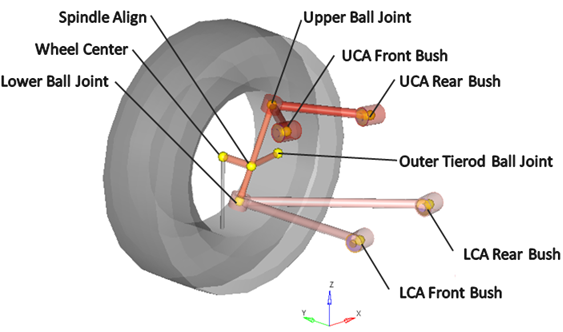
Figure 4. Right Side Principal Points – Front SLA Suspension with One (1) Piece Lower Control Arm
Bodies
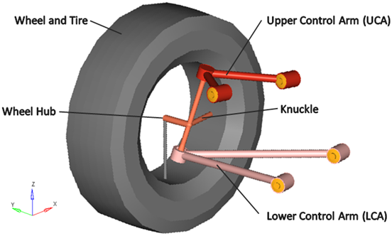
Figure 5. Right Side Bodies – Front SLA Suspension with One (1) Piece Lower Control Arm
Optional subsystems may add bodies to the suspension, for example the shock absorber adds two bodies: a shock rod and shock tube.
Bushings and Joints
| Label | Type | Body 1 | Body 2 | Point | Notes |
|---|---|---|---|---|---|
| Lower Ball Joint | Spherical | Knuckle | Lower Control Arm | Lower Ball Joint | |
| Upper Ball Joint | Spherical | Knuckle | Upper Control Arm | Upper Ball Joint | |
| Wheel Spindle | Revolute | Wheel Hub | Knuckle | Wheel Center | |
| Wheel Hub Fix Jt |
Fixed Joint | Wheel | Wheel Hub | Wheel Center | When the Spindle compliance option is set to Yes, the joint type changes to universal. |
| LCA Front Bush | Bushing | Lower Control Arm | Subframe, Vehicle Body or Ground | LCA Front Bush | When the Compliant option is set to No, this bushing becomes a revolute joint. |
| LCA Rear Bush | Bushing | Lower Control Arm | Subframe, Vehicle Body or Ground | LCA Rear Bush | When the Compliant option is set to No, this bushing is deactivated. |
| UCA Front Bush | Bushing | Upper Control Arm | Upper Control Arm | UCA Front Bush | When the Compliant option is set to No, this bushing becomes a revolute joint. |
| UCA Rear Bush | Bushing | Upper Control Arm | Subframe, Vehicle Body or Ground | UCA Rear Bush | When the Compliant option is set to No, this bushing is deactivated. |
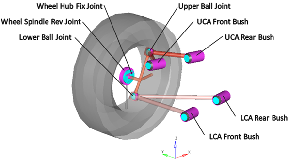
Figure 6. Right Side Joints and Bushings: SLA Suspension with One (1) Piece Lower Control Arm
Similar Suspensions
Front SLA (2pc LCA)
Rear SLA (1pc LCA)
Rear SLA (2pc LCA)