AutoBumpStop
The AutoBumpStop entity limits suspension travel in bump (also known as jounce). When the distance between two bodies becomes small, the AutoBumpStop applies a force to push the bodies apart.
$(ALTAIR_HOME)\hw\mdl\autoentities\properties\Bumpers-Jounce
AutoBumpStop Force
- Elastic force or stiffness
- Viscous force or damping
For a linear AutoBumpStop, the elastic force component is calculated using a third order polynomial, and for a non-linear AutoBumpStop the elastic force component is interpolated using the Akima method.
The viscous force component, when defined in the property file, is calculated directly from the damping rate in the property file and resultant instantaneous velocity between the two bodies.
Install Methods
The AutoBumpStop install method is at design position and is used to determine the distance at which the AutoBumpStop force starts acting.
- Impact Length Method
- When the impact length is of value ‘L’, the AutoBumpStop force acts when the distance between the two bodies is less than ‘L’.
- When the Impact Length install method is used, its value is directly used to
activate the AutoBumpStop force between the two bodies.
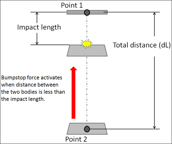
Figure 1. - Clearance Method
- When the Clearance method is used, the impact distance is calculated using:
- Where
(2) 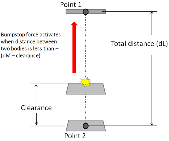
Figure 2.
Connecting an AutoBumpStop
Connections define the two bodies between which the BumpStop force acts and two points which are used to calculate the impact distance. The BumpStop force is activated when the distance between the bodies is less than a specified length. This distance is calculated based on the selected installation method.
AutoBumpStop Output Channels
Activating the Output check box adds an output request for the BumpStop resultant displacement, resultant velocity, and resultant force. The resultant displacement and velocity is measured between Point 1 and Point 2 and the resultant force is measured between Body 1 and Body 2.
| Type | Component | Quantity |
|---|---|---|
| REQSUB | RESULT(2) | Distance between Point 1 and Point 2 on the AutoBumpStop. |
| RESULT(3) | Rate-of-change-of-displacement between Point 1 and Point 2. | |
| RESULT(4) | AutoBumpStop force. | |
| RESULT(6) | Global X direction cosine of AutoBumpStop. | |
| RESULT(7) | Global Y direction cosine of AutoBumpStop. | |
| RESULT(8) | Global Z direction cosine of AutoBumpStop. |
AutoBumpStop Property File Example
The AutoBumpStop properties are stored in a AutoBumpStop Property File Example text file. When you resolve the property file field to a AutoBumpStop property file and submit the model to the solver, the solver reads the AutoBumpStop property file for use during simulation. If the units in the property file differ from the model units, the solver internally converts the AutoBumpStop properties to the model units. The properties file remains unchanged.
The AutoBumpStop properties file contains header, units, and curve blocks. The units block specifies the length, mass, force, time, and angle units employed in the file. The curve block holds a table of displacement against force values for the elastic force component and optionally a velocity against force values for the viscous force component.
$--------------------------------------------------------------------HEADER
[HEADER]
 FILE_TYPE     =  'bum'
 FILE_VERSION  =  4.0
 FILE_FORMAT   =  'ASCII'$
---------------------------------------------------------------------UNITS
[UNITS]
LENGTH =  'mm'
ANGLE  =  'degrees'
FORCE  =  'newton'
MASS   =  'kg'
TIME   =  'second'
$---------------------------------------------------------------------CURVE
[CURVE]
{ disp    force}
 0.0   0.0
 2.0   1.0
 4.0   2.0
 6.0   3.0
 8.0   4.0
10.0   5.0
20.0   6.0
30.0   7.0
40.0   8.0
50.0   9.0