| 1. | Launch HyperForm with the Incremental_Radioss user profile. |
| 2. | Select Tools > Blank Shape Predictor. |
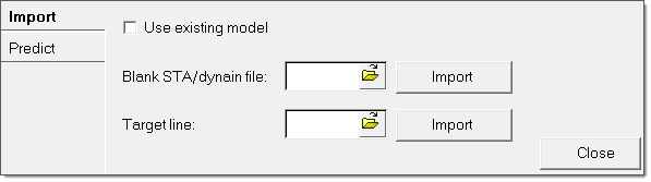
| 3. | In the Blank STA/dynain file field, navigate to the file, Form.sta, and then click Import. The .sta file is generated after the first forming simulation with the rectangular blank. |
| 4. | In the Target line field, navigate to the file, Design_CAD_Boundary.iges, and then click Import. |
| 5. | Click the Predict tab, and move your cursor to the field for Stage1. The cursor changes to a plus symbol, as you see in the figure in step 7. |
| 6. | In the Result file column for Stage1, click, and then navigate to the file, Line_Trace_Result_file.h3d, which is generated from the first iteration of the forming simulation. |
| 7. | Next to Select part, click the yellow Components button twice, and then click an element on the model in the graphics area. |
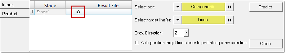
| 9. | Next to Select Target lines(s), click the Lines button twice, and then click lines >> displayed. |
| 10. | Click proceed >> Predict. HyperView opens in batch mode, and displays the predicted blank shape. |
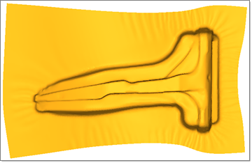
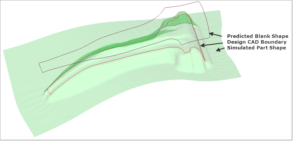
The following image shows you an overlay of the .sta file elements in transparent mode, the design CAD boundary, and the predicted blank shape:
|
| 1. | From the File menu, select Import > Model. |
| 2. | From the Import tab, navigate to Form_Dev_Blank.hf and click Import. This file loads on top of the existing .sta file and predicted blank outline. |
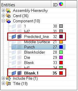
| 3. | In the Model browser, clear the display of the surface and elements for all the components except for Blank 1 and Predicted_line. |
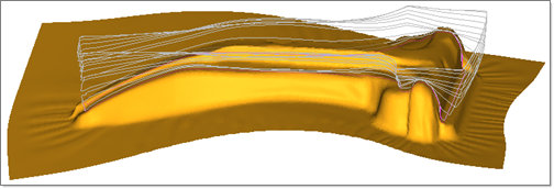
| 4. | From the Geometry menu, select Edit > Surfaces > Trim with Lines. On the panel that appears, set the options as you see outlined in red in the following image: |
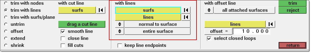
| 5. | Under the with lines header, click surfs, and then pick the blank surface from the screen. |
| 6. | Under the with lines header, click lines, and then select the predicted blank outline from the screen. |
| 7. | Click trim. After the trim operation, you can cut the required shape from the rectangular blank from the Delete panel. |
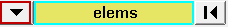
| 8. | To open the Delete panel, press F2. Click the extended entity selector and change the selection to elems. |
| 10. | Click Elems >> By Geom >> Surfs, and then pick the rectangular surface from the screen. |
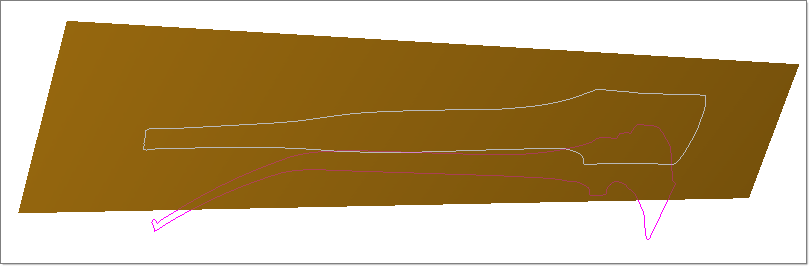
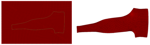
| 11. | Click add to selection and then click delete entity. The following figure shows you the new blank shape cut from the rectangular blank: |
| 12. | Use the new shape and follow HF-3010. Set up a new a forming simulation and compare the simulated shape with the design CAD boundary. Repeat Exercise 1. to predict the new shape until the simulated part shape matches with the design CAD boundary. |
|
|