Manufacturing Solutions

HF-3010: User Process

HF-3010: User Process

Previous topic Next topic Expand/collapse all hidden text  

HF-3010: User Process

Previous topic Next topic JavaScript is required for expanding text JavaScript is required for the print function  

This tutorial teaches you how to use the User Process utility to set up a model for a stamping analysis.


Benefits of the User Process

Create unique forming processes and save them as templates that you can re-apply with minimal or no input.
Include any number of tools.
Change the orientation of the tools.
Tool kinematics are unrestricted to conventional forming types such as Single- or Double-Action Draw.
The model setup is captured in the Auto Process and loaded into the User Process from the model definition.


Files for this Tutorial

forming_userprocess.hf

hmtoggle_plus1greyExercise 1: Set Up the Model for an Incremental Analysis
1.From the File menu, click Open.
2.Navigate to the model file, forming_userprocess.hf, and click Open.

Note: The model files for this tutorial are located in the file mfs-1.zip in the subdirectory \hf\Incremental\. See Accessing Model Files.

The model loads and looks something like this:

hf-3001-1

In the User Process browser, adjust the settings as follows:

1.Right-click Symmetry, and then select –X.
2.Double-click Animation: Count, and then change the value to 15.
3.For Draw direction, keep the default setting: Z.
4.For Motion Mode, select Velocity.
5.For Memory Mode, keep the default setting: Automatic.
6.Right-click Adaptivity, and then select On.
7.Right-click Process Type, and then select Forming > Single Action.


Complete the steps below to set up the blank parameters.

1.Right-click Blank, and then select Component > Sheet.
2.Under Blanks, right-click Material, and then select Database.

The Material Database dialog appears.

3.In the Steel folder, click CRDQ, and then click Select.

The material data is displayed in RADIOSS keyword format along with a curve that corresponds to the stress/strain data.

Notes:

You can maintain a custom material database. To do so, create the data in RADIOSS keyword format and copy it to
<HyperWorks>\hm\scripts\hyperform\automation\materialdb\materials\steel.
 
To define a user material library for incremental runs, define the following cards:

/BEGIN, /UNIT, /MAT, /FUNCT and /END

(Optional) Use any text editor to open and review CRDQ material data in the library.

<HyperWorks>\hm\scripts\hyperform\automation\materialdb\materials\steel\CRDQ.rad

#RADIOSS STARTER

##

## Radioss Input Deck Generated by HyperMesh Version  : 8.0SR1

## Generated using HyperMesh-Radioss Template Version : 8.0sr1

## Date: 08-07-2007   Time: 17:56:28

##

##==================================================================

/BEGIN

CRDQ.rad                                                                      

       51         0

##

##

/UNIT/MASS/1.0

/UNIT/LENGTH/1.0

/UNIT/TIME/1.0

##------------------------------------------------------------------

## Material Law No 43 HILL ORTHOTROPIC (Plasticity defined by a user function)

##------------------------------------------------------------------

/MAT/HILL_TAB/1

CRDQ                                                                                              

7.80000000000000E-09

           210000.0                 0.3

                1.6                 1.6                 1.6                 0.0


        1                                                

##------------------------------------------------------------------

## Functions

##------------------------------------------------------------------

##HWCOLOR curves 1 11

/FUNCT/1

crdq_stress_strain                                                                                

                0.0               185.0

               0.05          293.188135

                0.1          339.127251

………………………………………………………
………………………………………………………

##------------------------------------------------------------------

## End Of Radioss Block Deck

##------------------------------------------------------------------

/END


Note: An easy way to create your own material is to replace the data of an existing material with your data, and then save the material with a new name.
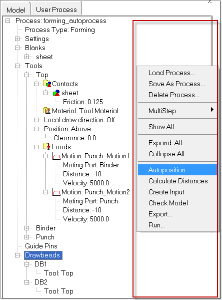
4.In the User Process browser, double click Thickness: 1.0 and change the value to 1.5.


1.Right-click Die_sad, and then select Component > Top.
2.Under Binder, click the field, Force:-1000.0, click the value -1000.0, and then enter the new value: -10000.

Drawbeads Editor Toolbar

The following tools are available on the Drawbeads Editor toolbar:

Tool

Function

db_disp_sel

In the drop-down menu, select Both to display both the drawbeads and lines in the model representation, Drawbeads to display only the drawbeads in the model representation, or Lines to display only the lines in the model representation.

create

Create a drawbead by clicking points to define a line. When the points are in place, click Create to set the line and create a corresponding drawbead based on the line.

add

Click to add a drawbead to the table. Then complete the fields for the row in the table to define the drawbead.

select_line

Click lines to select them. Lines appear as blue dashes. When they are selected, they become yellow.

add_lines

Click to add a drawbead for each line.

delete

Click to delete the active drawbead from the table. The active drawbead in the table has a gray arrow next to it.

delete_all

Click to delete all drawbeads.

select

Click on a drawbead in the model to select it.

move

Click a drawbead to select it and then click and drag endpoints to change the size of the drawbead.

split

Click a point on a drawbead to split the drawbead into two drawbeads at that location.

combine

Click two when the button is selected to combine them into a single drawbead.

undo_normal

Click the button to undo the last action in the Drawbeads Editor.

db_mode_sel

In the drop-down menu, select:

Force to set the force calculation mode as the default, which requires that you supply values for restraining and closure forces. You can also use the Drawbead Calculator to determine values.

or

%-lock to set the force calculation mode as percent lock, which applies force as a percentage of the required necking force.

viewFit-24

Click to fit the model to the current window size.

viewZoom-24

Click once to fit the model in the window. Click and drag to area select and zoom.

viewPan-24

Click and drag to move the viewing area of a zoom view.


1.From the tree in the User Process browser, right-click Drawbeads, and then select Edit Drawbeads.

HF-3002-08

2.Click the pencil create tool.
3.On the model graphics, draw a line:

HF-3002-09

4.To complete the line, select the points, and then click create. Notice the line color changes to yellow and the drawbead table is displayed:

HF-3002-10

5.Repeat steps 2 - 4 to create DB2 and DB3:

HF-3002-12

hf-3002-13

6.Under the Name column, click the space left of DB1. Notice that an arrow appears and the corresponding drawbead line changes from green to yellow in the model graphics.
7.After the Tstart column, in row DB1, click the elipses button . The Drawbead Calculator opens:

HF-3002-14

8.To accept the current settings, click arrow_right_md.

Notice that all of the conditions are calculated for the given geometry, blank material, and thickness:

HF-3002-15

9.Click Back.

Notice that the calculated restraining force and normal force are automatically filled in.

10.In the Drawbeads Editor, follow the same steps for DB2 and DB3 and enter values for all drawbeads.
11.To create the force curves for the drawbeads, click Update.
12.To close the Drawbeads Editor, click Back.
Note:In the Model Browser, expand the Components folder. You will find three components: ^db_line for DB1, ^db_line for DB2 and ^db_line for DB3. These components are generated automatically, and correspond to the three drawbeads.


1.Right-click anywhere inside the red boundary and select Autoposition as shown below:

HF-3002-16

The status of auto positioning is shown and updated at the left hand bottom corner of the window. Done indicates that tools have been successfully positioned with respect to blank.

2.Right-click any where in the red boundary as shown in the above figure and select Run.
3.At the prompt to create input, click Yes.
4.Enter a filename, and click Save.

This will create a RADIOSS input deck which consists of two files:

<file name>_0000.rad and <file name>_0001.rad

5.Right-click anywhere in the red boundary as shown in the above figure and select Check Model. This action checks the model for any errors and opens a box that includes the following:
A Sequence tab that displays the tool kinematics sequence
A Messages tab that displays errors in the setup, if any.
Preview animation of the tool kinematics.

HF-3002-17

6.Click the Binder motion curve block to highlight the border with thick black line.
7.To change the tool motion interactively, click and drag the thick black border.
8.Right-click Process, and then Save As Process:

HF-3002-19

9.Enter User_Process in the file browser, and then click Save.


hmtoggle_plus1greyExercise 2: Retrieve the Saved Process to Setup a Second Model

This exercise will make use of the model Forming_ReUse_User_Process.hf.

1.Click on File and select Save As… to save the existing file in the session.
2.Click on the New .hm File iconfileNew-24. This deletes the existing model from the session. Note that the parameters under the process tree is empty.
3.Click on Open Folder icon fileOpen-24 and browse for the file Forming_ReUse_User_Process.hf. Double-click to open the file.
4.Right-click on Process and select Load Process… as shown below.

HF-3002-20

5.Browse for the file User_Process.up and double-click the file. A dialog box appears as shown below. Click OK to bring the process file into HyperForm session.

HF-3002-21

Notice that the process tree gets populated as per the settings of the imported process file.

The model and the retrieved process in the session look as below:

1.Right-click on Symmetry and select No.
2.Right-click on the component name Sheet and select Component and select Part.
3.Right-click on the component named Top and select Component and select Die.
4.Right-click on the component named Die and select Component and select Binder.
5.Right-click on the component named Punch and select Component and select Punch.
6.Follow points 1 through 6 of step 5 from Exercise 1 to Autoposition, create input, export and run the model.

Return to Incremental Tutorials