| 1. | From the File menu, click Open. |
| 2. | Navigate to the model file, forming_autoprocess.hf, and click Open. |
Note: The model files for this tutorial are located in the file mfs-1.zip in the subdirectory \hf\Incremental\. See Accessing Model Files.
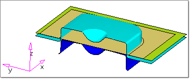
The model loads and looks something like this:
|
| 1. | On the toolbar above the modeling window, click the Single Action Draw  icon. icon. |
| 2. | On the error message that displays, click OK. |
The Autoprocess panel appears:
Note:
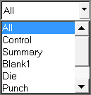
| • | Components are recognized if the names are identical or have common letters to the tool nomenclature in the Auto Process macro such as Blank, Die, Punch and Binder. |
| • | The colors of the components are picked up by the schematic of Single Action Draw inside of Auto Process. |
| • | Parts that are not recognized appear with dashed lines within the Auto Process image. |
|
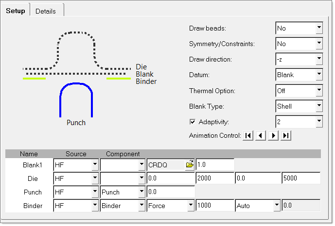
| 1. | Check that the Process field is set to Single Action Draw. |
| 2. | For Draw beads, select No. |
| 3. | For Symmetry/Constraints, select –x (Symmetric to YZ plane). |
| 4. | For Draw direction, select –z. |
Note: In a Single Action Draw, the die closes in by following the negative Z direction.
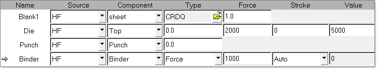
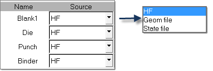
| 5. | Verify that the file type is HF in the Source file column for Blank1, Die, Punch and Binder. You have two options: HF and Geometry file. For Blank1 you have an additional option of STATE file. |
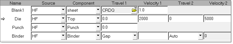
| 6. | Use the pull down selector  in the Component column and select the components sheet, Top, Punch and Binder as you see in the following image: in the Component column and select the components sheet, Top, Punch and Binder as you see in the following image: |
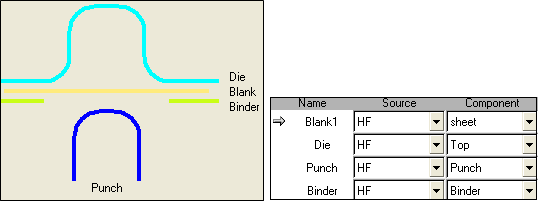
Notice the components are recognized with a solid line in the Auto Process image.
| 7. | Click the Autoposition button. |
| 8. | In the warning dialog that appears, click Proceed, and then do one of the following: |
| • | To apply the tool travel values calculated by the utility, click Apply. |
| • | To apply values that are user-defined, click Cancel, and then select a tool Name to activate the column headings for that tool. Enter the appropriate values in the travel fields, and then click Apply. |
|
| 1. | Click the space next to the component Blank1. The arrow  activates the component and lets you modify parameters for that component. activates the component and lets you modify parameters for that component. |
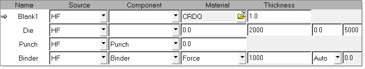
| 2. | Define the material and thickness for the blank: |
| • | For Material, select CRDQ steel (default). |
| • | For Thickness, enter 1.0 (blank thickness in mm). |
| • | Define the other fields as you see in the image above. |
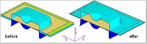
| 3. | Click the Autoposition button. |
| • | Travel distances are calculated and the respective boxes are populated accordingly. |
| • | All tools move to the appropriate location so that they just touch the blank as you see in the following image: |
Note: In order to use your own values for tool travel and velocity, simply edit the values in the respective boxes, and then click Apply. Do not click Autoposition.
|
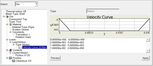
| 1. | Click the space next to Die. The arrow activates the component and enables you modify parameters for that component. |
| • | Travel 1: The distance the die travels towards the binder (mm). |
| • | Velocity 1: The velocity at which the die travels towards the binder. The suggested velocity is 2000 mm/s. |
| • | Travel 2: The distance the die travels towards the punch (mm). Enter 70.0. |
| • | Velocity 2: The velocity at which the die travels towards the punch. The suggested velocity is 5000 mm/s. |
|
| 1. | Click the space next to Punch. The arrow activates the component and lets you modify parameters for that component. |
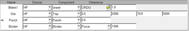
| • | Clearance: The distance between the punch and the blank at the initial configuration. Keep default setting 0.0. |
|
| 1. | Click the space next to Binder. The arrow activates the component and lets you modify parameters for that component. |
Type: The type can be either Force, or Gap:
| • | Force: In this method, a force is applied to keep the binder closed. |
| • | Gap: Gap (mm) is defined as the actual physical distance between the binder and die that is maintained after the binder closure until the draw is completed, after subtracting the blank thickness. |
| 2. | Select the type as Force, and in the Force field, type 100000. |
|
| 1. | Click the Blank1 field again. Under Material, click  to open the material database: to open the material database: |
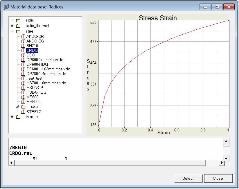
| 2. | In the steel folder, click CRDQ. |
The material data is shown in RADIOSS keyword format along with a curve that corresponds to the stress/strain data. Click Select to make the selection.
Notes:
You can maintain a custom material database. To do so, create the data in RADIOSS keyword format and copy it to
<HyperWorks>\hm\scripts\hyperform\automation\materialdb\materials\steel.
To define a user material library for incremental runs, define the following cards:
/BEGIN, /UNIT, /MAT, /FUNCT and /END
| 3. | (Optional) Use any text editor to open and review the CRDQ material data in the library. |
<HyperWorks>\hm\scripts\hyperform\automation\materialdb\materials\steel\CRDQ.rad
#RADIOSS STARTER
##==================================================================
##
## Radioss Input Deck Generated by HyperMesh Version :
## Generated using HyperMesh-Radioss Template Version :
## Date: 01-30-2009 Time: 17:56:28
##
##==================================================================
/BEGIN
CRDQ.rad
51 0
##
##
/UNIT/MASS/1.0
/UNIT/LENGTH/1.0
/UNIT/TIME/1.0
##------------------------------------------------------------------
## Material Law No 43 HILL ORTHOTROPIC (Plasticity defined by a user function)
##------------------------------------------------------------------
/MAT/HILL_TAB/1
CRDQ
7.80000000000000E-09
210000.0 0.3
1.6 1.6 1.6 0.0
1
##------------------------------------------------------------------
## Functions
##------------------------------------------------------------------
##HWCOLOR curves 1 11
/FUNCT/1
crdq_stress_strain
0.0 185.0
0.05 293.188135
0.1 339.127251
………………………………………………………
………………………………………………………
##------------------------------------------------------------------
## End Of Radioss Block Deck
##------------------------------------------------------------------
/END
| 4. | Click Close to close the dialog. |
|
When Drawbeads is set to yes in the Auto Process, you can launch the Drawbeads Editor using the  button. The Drawbeads Editor helps you quickly create analytical drawbeads from lines and rapidly manipulate them. You can also edit drawbeads by clicking in the modeling area. button. The Drawbeads Editor helps you quickly create analytical drawbeads from lines and rapidly manipulate them. You can also edit drawbeads by clicking in the modeling area.
| 1. | To create the Drawbeads row in the table, in the Auto Process panel, next to Drawbeads, select Yes. |
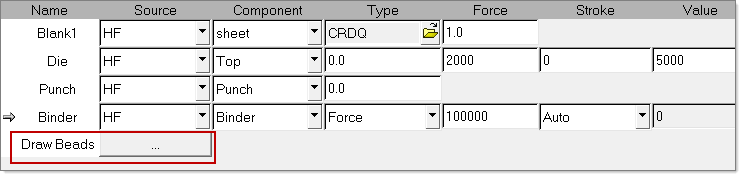
| 2. | To launch the Drawbeads Editor tool, click  . . |
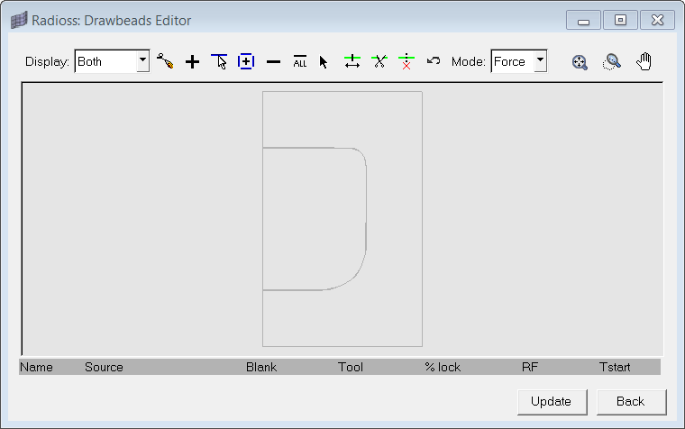
The following tools are available on the Drawbeads Editor toolbar:
Button
|
Function
|
|
In the drop-down menu, select Both to display both the drawbeads and lines in the model representation, Drawbeads to display only the drawbeads in the model representation, or Lines to display only the lines in the model representation.
|

|
Create a drawbead by clicking points to define the line. When the points are in place, right-click to set the line and create a corresponding drawbead based on the line.
|

|
Click to add a drawbead to the table. Then complete the fields for the row in the table to define the drawbead.
|

|
Click lines to select them. Lines appear as blue dashes. When they are selected, they become yellow.
|

|
Click to add a drawbead for each line.
|

|
Click to delete the active drawbead from the table. The active drawbead in the table has a gray arrow next to it.
|

|
Click to delete all drawbeads.
|

|
Click on a drawbead in the model to select it.
|

|
Click a drawbead to select it and then click and drag endpoints to change the size of the drawbead.
|

|
Click a point on a drawbead to split the drawbead into two drawbeads at that location.
|

|
Click two drawbeads when the button is selected to combine them into a single drawbead.
|

|
Click the button to undo the last action in the Drawbeads Editor. You can also right-click to sequentially remove the most recently created points.
|

|
In the drop-down menu, select:
Force to set the force calculation mode as the default, which requires that you supply values for restraining and closure forces. You can also use the Drawbead Calculator to determine values.
or
%-lock to set the force calculation mode as percent lock, which applies force as a percentage of the required necking force.
|

|
Click to fit the model to the current window size.
|

|
Zoom feature. Click once to fit the model in the window. Click and drag to draw a rectangle to zoom in on that selection area.
|

|
Click and drag to move the viewing area when the model is zoomed in.
|
| 4. | Click the pencil button  . . |
| 5. | Graphically draw a blue line on simplified graphical representation of the model in the top area of the Drawbeads Editor, as shown below. |
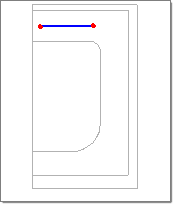
| 6. | After selecting the points, click the create button to complete the first line. Notice the color changes to yellow and the drawbead table displayed. |

| 7. | Repeat the same steps to create DB2 and DB3, as shown below. |
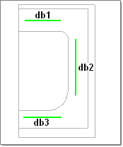
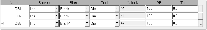
| 8. | Click the space left of DB1. Notice the corresponding drawbead line changes from green to yellow in the graphics region. |
| 9. | Click  after the Tstart column in the same row as DB1. This will open the Drawbead Calculator as shown below. after the Tstart column in the same row as DB1. This will open the Drawbead Calculator as shown below. |
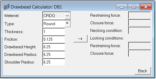
| 10. | Accept the current settings and click  . Notice all the resultant conditions are calculated for the given geometry, blank material, and thickness. . Notice all the resultant conditions are calculated for the given geometry, blank material, and thickness. |
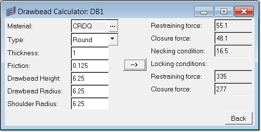
Notice that the calculated restraining force and normal force are automatically updated.
| 12. | In the Drawbeads Editor, follow the same steps for DB2 and DB3 to input values for all drawbeads. |
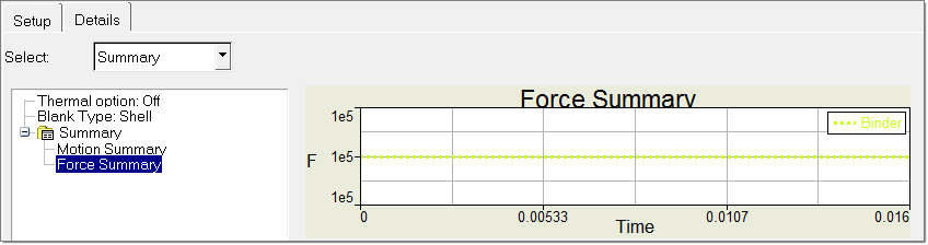
| 13. | Click Update to create the force curves for the drawbeads. |
| 14. | Click Back to return to the Auto Process setup page. |
| 15. | In the Auto Process panel, click Apply. |
| Note: | In the Model Browser, expand the Component folder and locate three components: ^db_line for DB1, ^db_line for DB2 and ^db_line for DB3. These components are generated automatically, and correspond to the three drawbeads. |
|
|