This tutorial shows you how to set up a simple tube bending analysis and assumes basic understanding of the tube bending process.
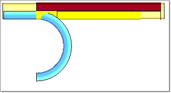
For this tutorial, you create the following model and set up a tube bending analysis.
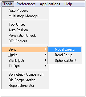
From the Tools menu, right-lick Bend and select Model Creator:
From the Setup menu, you can access the panels for this tutorial:
|
| 1. | From the Tools menu, select Bend and then select Model Creator. The following panel is displayed. |
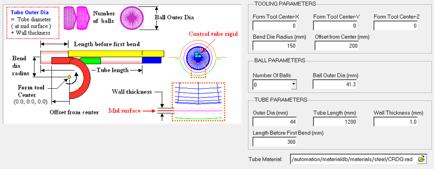
| 2. | Enter the values shown in the fields below: |
Field Description
|
Values
|
Tooling Parameters
|
Form Tool Center – X
|
0.0
|
Form Tool Center – Y
|
0.0
|
Form Tool Center – Z
|
0.0
|
Bend Die Radius (mm)
|
163
|
Offset From Center (mm)
|
100
|
Ball Parameters
|
Number of Balls
|
2
|
Ball Outer Dia (mm)
|
70.3
|
Tube Parameters
|
Outer Dia (mm)
|
76.2
|
Tube Length (mm)
|
750
|
Wall Thickness (mm)
|
2.6
|
Length Before First Bend (mm)
|
156.6
|
The graphical definition of all parameters is illustrated in the image below.
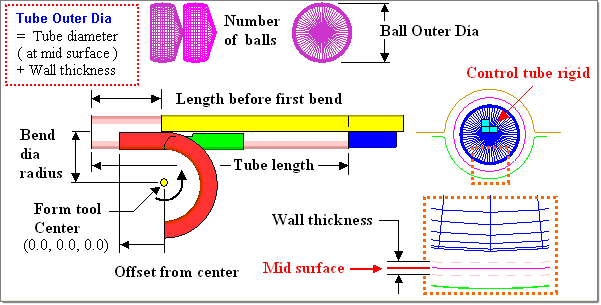
Note: Outer Dia = Tube diameter ( at mid surface of a tube) + Wall Thickness.
|
| 1. | From the Tools menu, select Bend and then select Bend Setup. Type the file name as tube_bending and specify the required location to save the file. |
| 2. | After saving, the bend setup utility appears: |
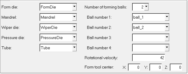
Notice that some component selections are already done.
| 3. | Set the Number of Bends field to 3 to specify the number of bends. |
| 4. | Enter the following in the table to provide the bend sequence data: |
Translate
|
Rotate
|
Bend Angle
|
156.2
|
0
|
56.2
|
87.2
|
-49.2
|
50.2
|
99.7
|
126.1
|
29.8
|
| 5. | Click Run. The folder where you saved the file will have <filename>_0000.rad and <filename>_0001.rad installed. The number of <filename>_000* files depends on the number of bends in the Bending setup. In this case, it is 6 files – 0001.rad, 0002.rad, 0003.rad, 0004.rad, 0005.rad and 0006.rad files. |
The tube bending problem has been set up completely.
| Note: | All tool parameters from the Bending Model Creator dialog are automatically applied to the "Bending Setup". However, if you create the tube and tool meshes without using the Bending Model Creator dialog, you will need to manually modify [install_directory]\scripts\hyperform\hydroforming\TubeBendingInitDefaults.dat to suit your needs. |
|
|
| 1. | From the Tools menu, select Bend and then select Bend Setup. The following dialog appears: |
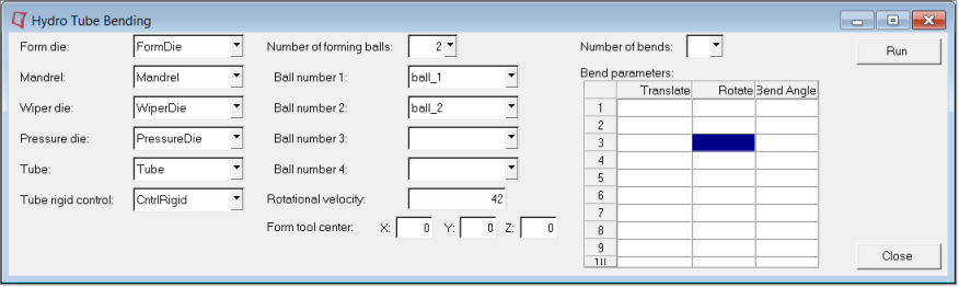
| 2. | Make the following component selections in the Hydro Tube Bending dialog by using the selector for the corresponding fields. |
Selector Label
|
Component
|
Form die:
|
FormDie
|
Mandrel:
|
Mandrel
|
Wiper die:
|
WiperDie
|
Pressure die:
|
PressureDie
|
Tube:
|
Tube
|
Tube rigid control:
|
CntrlRigid
|
Number of forming balls
|
2
|
Ball number 1:
|
ball_1
|
Ball number 2:
|
ball_2
|
Number of bends
|
3
|
| 3. | Enter the following in the table for bend sequence data: |
Translate
|
Rotate
|
Bend Angle
|
156.2
|
0
|
56.2
|
87.2
|
-49.2
|
50.2
|
99.7
|
126.1
|
29.8
|
The tube bending problem has been set up completely.
| Note: | All tool parameters from the Bending Model Creator dialog are automatically applied to the "Bending Setup". However, if you create the tube and tool meshes without using the Bending Model Creator dialog, you will need to manually modify [install_directory]\scripts\hyperform\hydroforming\TubeBendingInitDefaults.dat to suit your needs. |
|
|
|
| 1. | From the File menu, select Save As…. |
| 2. | Use the file browser to save the file as tube_bending_complete.hf. |
|
| 1. | Run the analysis from the RADIOSS Manager, which you can access from Start > All Programs > Altair HyperWorks. |
| Note: | Do not use the Run function from the Utility Menu or the main panel area. This will rewrite the D00 and D0* files created from the Bending setup. |
|
| 2. | Click run. An LS-DYNA input file named forming_complete.bdf is generated. The file can be submitted to LS-DYNA for solver analysis (in the Incremental_LS-DYNA user profile). |
|
Return to Incremental Tutorials


