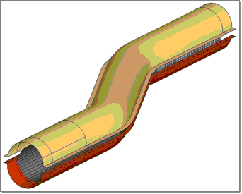
This tutorial shows you how to set up a basic hydroforming analysis for a tube.
Hydroforming is a metal forming process that uses fluid pressure to shape a metal piece into a specified form. The process begins with placing a metal piece in a blank holder over a punch, followed by moving the blank holder and punch next to a fluid filled dome. Pressure inside the dome is increased to form the part. As the punch moves against the diaphragm of the dome, the pressure inside the dome is adjusted to form the metal into the desired shape.
Prerequisites
Familiarity with basic HyperForm functionality such as meshing and mesh editing. If you need help on these topics, refer to the corresponding tutorials in the online help.
Files for Incremental_RADIOSS
| • | hydro_die_geom_radioss.igs |
RADIOSS Setup model
Files for Incremental_Dyna
LS-DYNA Setup model
This tutorial uses the following panels which are available in the Setup menu:
|
| 1. | Create a working directory where you intend to run the simulation for this tutorial. |
| 2. | Copy and unzip the file, tube_radioss.zip, into your working directory. |
Note: The model files for this tutorial are located in the file mfs-1.zip in the subdirectory \hf\Incremental\. See Accessing Model Files.
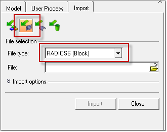
| 3. | Click the Import Solver Deck icon  . The Import tab opens. Select the options as you see in the following figure: . The Import tab opens. Select the options as you see in the following figure: |
| 4. | Browse to the file for your user profile, tube_radioss.sta or tube_dynain. |
| Note: | During the import of the sta/dynain file, only the node and element definitions are read into HyperForm. The adaptive constraints, initial stress, and initial strain quantities are automatically placed into a new file called filename.sta.hmx/dynain.hmx. This extra information should be automatically included in the new setup by the #INCLUDE in the D00 0000.rad file for RADIOSS or *INCLUDE card for LS-DYNA. |
|
|
| 1. | In the Model browser, expand the Component folder. |
| 2. | Right-click component 1, and select Rename. |
| 3. | Enter the name, Tube, and click ENTER. |
|
| 1. | From the Setup menu, click Sections. The Section Definition panel is displayed. |
| 2. | In the section field, type tube_section. |
| 3. | In the thickness: field, type 1.3 (mm). |
| 4. | Click card image: and select the respective card image from the list: |
| • | For RADIOSS, select SH_ORTH |
| • | For LS-DYNA, select SectShll. |
|
| 1. | From the Setup menu, click Materials. The Material Definition panel displays. |
| 2. | In the material: field, type CRDQ_steel. |
| 3. | Click card image:, and select the respective card image from the list: |
| • | For RADIOSS, select HillOrthotropic Tabulated |
| • | For LS-DYNA, select TransAnsioElasticPlastic. |
| 5. | In the curve: field, type stress_strain_curve. |
| 6. | In the sigy = field, enter 185. (MPa) |
| 7. | In the k = field, enter 550. (MPa) |
| 8. | In the n = field, enter 0.21. |
| 12. | For LS-DYNA, click edit card and set Lankford coefficient (R) to 1.6. |
|
| 1. | From the Setup menu, click Components. |
| 2. | Double-click component: and select Tube. |
| 3. | Click section: and select tube_section. |
| 4. | Click material: and select CRDQ_steel. |
| 6. | Select the adaptive check box. |
| Note: | By default, three levels of adaptivity are enabled. You can change the adaptive levels via the Control Card panel, and editing the parameter LevelMax in the card /ADMESH/GLOBAL for RADIOSS and the parameter MAXLVL in the Adaptive card for LS-DYNA. Refer to the RADIOSS/LS-DYNA manual for more details. |
|
|
| 1. | Click on the Import Geometry icon  . The Import tab opens. . The Import tab opens. |
| 2. | Click the file browser icon  and browse to find the file hydro_die_geom_radioss.igs/hydro_die_geom.igs and double-click to open the file. and browse to find the file hydro_die_geom_radioss.igs/hydro_die_geom.igs and double-click to open the file. |
|
| 1. | In the Model Browser, expand the Component folder. |
| 2. | Right-click on the component lvl2 and select Rename. |
| 3. | Enter the new name as upper_die and click Enter. |
| 4. | Right-click on the component lvl3 and select Rename. |
| 5. | Enter the new name as lower_die and click ENTER. |
|
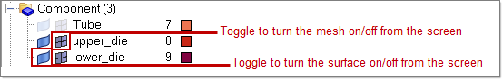
| 1. | In the Model Browser, click the icons as shown in the figure below to turn on lower_die and upper_die components. |
|
| 1. | In the Model Browser, under the Components folder, right-click on Upper Die and select Make Current. |
Note: This sets the current working component to be upper_die.
|
|
R-Mesh is a tool meshing utility available from the Mesh menu that allows you to specify several parameters to create the mesh. The macro is intended for generating rigid tool meshes for incremental analysis. For incremental analysis, the meshing parameters default settings are Minimum Edge: 0.5, Maximum edge: 30.0, Chordal deviation: 0.1, and Fillet angle: 15.0.
The four parameters are defined as shown in the interface as shown below.
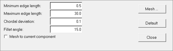
| 1. | From the Mesh menu, click R-Mesh. |
The default parameters can be used here.
| 2. | Select the Mesh to current component check box. |
| 4. | Select the yellow surfs button and select by collector. |
| 5. | Select the upper_die component and click proceed. |
|
| 1. | Set the lower_die component as the default working component. |
| 2. | Mesh the lower_die surface using R-Mesh. |
|
| 1. | Click Tools > Hydro > Hydro Setup. |
| 2. | A window pops up asking you to save the file. Type the file name as tube_hydro_radioss_complete and specify the required location to save this file. The HydroForming utility displays as below: |
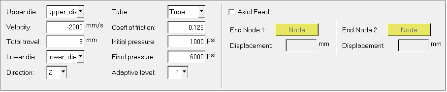
| 3. | For Upper Die:, choose the upper_die component. |
| 4. | Click Velocity: and type -2000. (mm/s) |
| 5. | Click Total travel: and type 8. (mm) |
| 6. | For Lower Die:, select the lower_die component. |
| 7. | For Tube:, select the Tube component. |
| 8. | For Adaptive levels:, change from the default of 3 to 1. |
| 9. | Click Coeff of friction: and type 0.125. |
| 10. | Click Initial pressure: and type 1000. (psi) |
| 11. | Click Final pressure: and type 6000. (psi) |
| 12. | Click Run to set up the hydroforming pressure loads. |
Notice the pressure curve and velocity curve are set on screen.
Note: For RADIOSS, D00 and D01 files are created at this step. Save the file as in Step 13 and directly use the RADIOSS Manager to run these files. The RADIOSS Manager can be accessed from Start > All Programs > Altair HyperWorks.
Do not execute the Run command either from the Utility Menu or the main panel area.
|
|
| 1. | Click File > Save As.... |
| 2. | Enter the file name as tube_hydro_complete.hf. |
|
| 1. | Under Setup, click Run. |
| 3. | Click applied comps: comps and select Tube. |
| 5. | Select the DYNA check box. |
A message appears stating: "The entity set has been created."
Note: At the end of the computation, LS-DYNA will write out a file named "dynain". This file contains all the stress and strain information necessary to perform subsequent operations. This file can be read directly by HyperForm and is essential for performing multi-stage setups.
|
| 8. | Click dyna file and specify the name tube_hydro_complete. |
| 9. | Click run. A dyna input file tube_hydro_complete.bdf is generated. The file can be submitted to LS-DYNA for solver analysis. |
|
Return to Incremental Tutorials


