|
»Click here to display Table of Contents«
|

Midplane Wizard |

|

|

|

|
|
Midplane Wizard |
|
|

|

|
|
»Click here to display Table of Contents«
|
Midplane Wizard |
|
|
|
|
|
Midplane Wizard |
|
|
|
|
The Midplane Wizard is used to create midplane mesh model data decks for injection molding analysis starting from solids, surfaces enclosing a volume, surfaces representing a midplane or midplane surface mesh. This wizard will guide you to create midsurface, midplane mesh, and assign property cards to the elements.
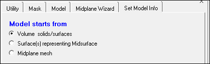
The Midplane Wizard can be used in four ways:
| • | Start from clean set of solids to extract and create midplane input data deck |
| • | Start from clean set of surfaces which encloses a volume to extract and create midplane input data deck |
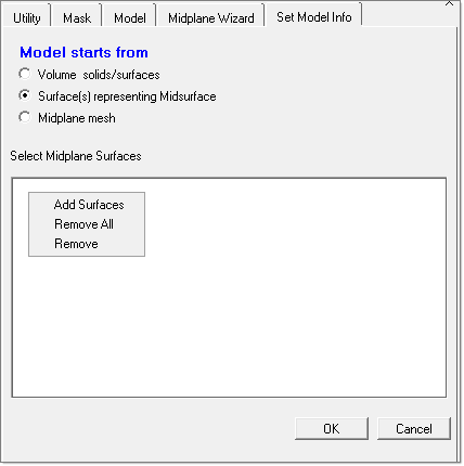
| • | Start from surface which represents the midplane surfaces to complete a midplane input data deck |
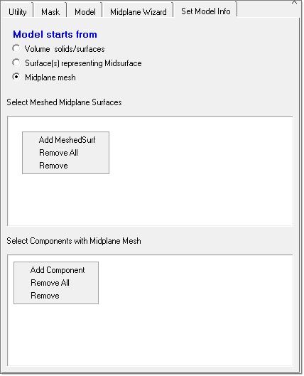
| • | Start from mesh which represents the midplane to complete a midplane input data deck |
When you click on the Midplane Wizard macro, it opens a separate tab showing all the steps in the Midplane Wizard. You must complete each one of these simple steps, one at a time, for the Midplane Wizard to run successfully. No knowledge of HyperMesh is necessary to complete these steps.
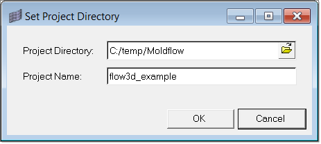
Specify the appropriate project directory and a suitable project name for the job to begin. Browse the folder by clicking on the folder icon in the window and select the directory.
Click OK to save the settings and Cancel to abort the operation without saving.
|
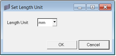
Select the suitable units using the Set Length Unit dialog. After selecting the units, click OK to save the selection. This information will be used at the time of export to convert the nodal coordinates to SI units.
|
|
||||||||
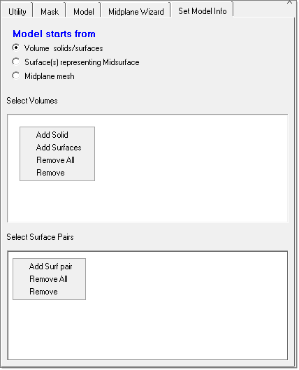
This step extracts the midsurface from the selected solid/surface volumes. Use this only with models that start from volumes. This option will not be highlighted until you complete the next two steps.
|
This step opens the Midsurface panel, where you can correct the extracted midsurface. In order use this panel and repair the errors in the created midsurface, you should be familiar with the features in this panel. Read the Midsurface panel online help for more information.
|
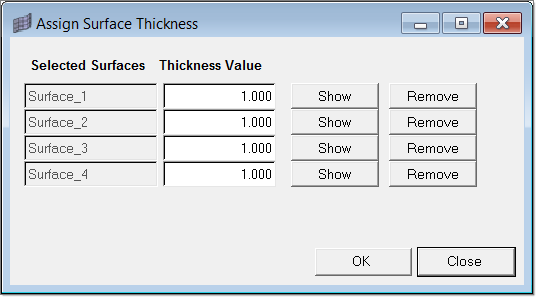
This option is available only when you start with existing midsurfaces. Use this option to specify a thickness for each surface. This step is necessary only when the surface does not have embedded thickness or when you want simplify if it by using an uniform thickness.
|
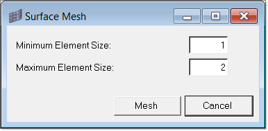
This panel is used to mesh the midsurfaces. Specify a minimum and maximum thickness. The meshing algorithm internally orders all the surface edges based on length and interpolated the edge density based on these values.
|
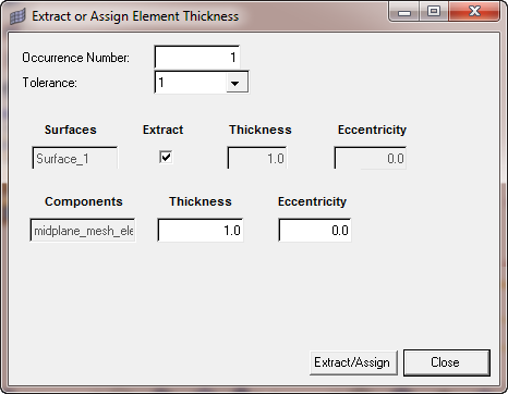
This step automatically creates property cards for all the midplane elements and assigns it to them. At the end of this step, it also shows the contour of element thickness. If you start the model from an existing mesh (on a surface or not on a surface), the following dialog is shown to enable the thickness specification.
|
In this step, you are guided to create a feed system using beam elements. Solids representing the shape of the beam elements are created solely for visual representation. These solids are not exported with the data deck. You can either choose to create a generic feed system or a structured feed system. More details about this step can be found in the topic Feed System Wizard. The steps outlined in that section are identical to those in this wizard.
|
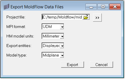
Use this dialog to export the model and create the .udm file, which can then be imported into Moldflow and solved.
|