|
»Click here to display Table of Contents«
|

Flow 3D Wizard |

|

|

|

|
|
Flow 3D Wizard |
|
|

|

|
|
»Click here to display Table of Contents«
|
Flow 3D Wizard |
|
|
|
|
|
Flow 3D Wizard |
|
|
|
|
The Flow3D Wizard is used to create solid (3D) mesh model data decks for injection molding analysis starting from solids, surfaces or surface mesh. Every solid mesh is placed in a component collector with the name flow3d_mesh#n, where n can be any integer depending on the number of solids in the model or number of set of closed surfaces or surface mesh. For solids, if the feed system is also solid, then the Flow3D Wizard meshes the feed system first to capture the material flow properly and then meshes the part.
The Flow3D Wizard can be used in three ways:
| • | Start from clean set of solids to complete a Solid(3D) input data deck |
| • | Start from clean set of surfaces to complete a Solid(3D) input data deck |
| • | Start from surface mesh of closed surfaces to complete a Solid(3D) input data deck |
When you click on the Flow3D Wizard macro, it opens a separate tab showing all the steps. You must complete each one of these simple steps, one at a time, for the Flow3D Wizard to run successfully. No knowledge of HyperMesh is necessary to complete the steps.
If the model has surface mesh, then the Surface Mesh step is disabled. The steps completed and the status is indicated in the status panel below the project panel. Click the Summary button to display information regarding element Statistics. Click the Close button to close the Flow3D Wizard tab and return to the Utility menu.
Information created will be retained even when you close and re-open the tab, or when you close HyperMesh and start it again using the same model file.
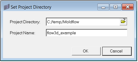
Specify the appropriate project directory and a suitable project name for the job to begin. Browse the folder by clicking on the folder icon in the window and select the directory.
Click OK to save the settings and Cancel to abort the operation without saving. |
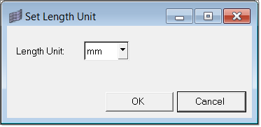
Select the suitable units using the Set Model Unit dialog. After selecting the units, click OK to save the selection. This information will be used at the time of export to convert the nodal coordinates to SI units.
|
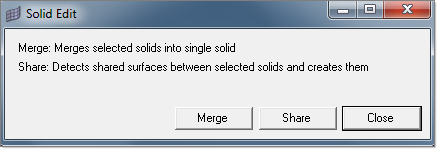
This step is applicable only for models with solids. It is an optional step.
You can access a more comprehensive set of solid editing features from the Solid Edit menu panel.
|
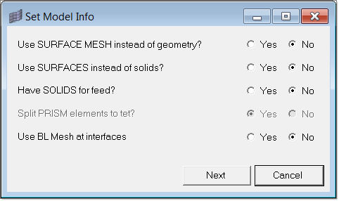
Depending on how the 3D volume is represented in your model, the steps involved in creating a 3D mesh will vary. The volume to be meshed may be represented in one of the following ways:
In this step, five questions define the model under consideration.
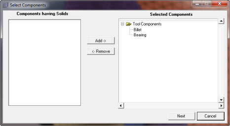
When you click Next, the component collectors for Feed and Part and Feed Inlet surfaces need to be specified in the Select Components dialog, as shown below.
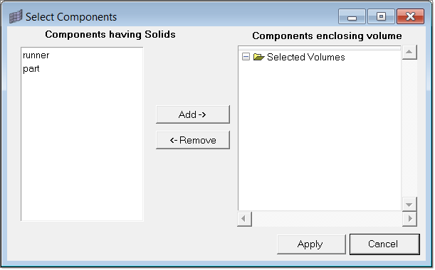
For a model that does not have solids for the feed, the Select Components window will appear in the following fashion.
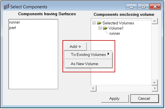
For a model with surfaces or surface mesh, the Add button can be used to add components to new or existing volumes.
|
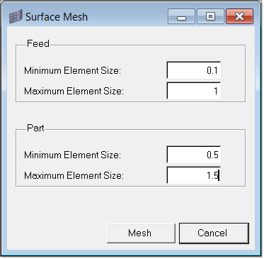
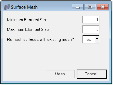
Starting with Solids for Feed and PartIn the Surface Mesh dialog, you will have to specify minimum and maximum element sizes for both feed and part. Click Mesh to generate a 2D mesh.
Surface Mesh (Starting with Solids for Part only or Starting with Surfaces)When you start with solids only for part or with surfaces, then the following dialog comes up.
Specify the minimum and maximum element size for the entire model. If you set the last option No, then surfaces having mesh will not be considered for meshing. Click Mesh to generate 2D mesh.
|
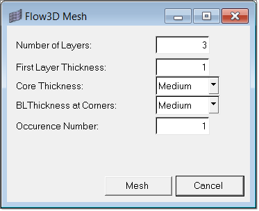
In the Flow3D Mesh dialog, you will have to specify the following data:
Click Mesh to generate Flow3D mesh. If the geometry is not clean or closed, then the Flow3D mesh may fail. Each Flow3D mesh is placed in a component collector named flow3d_mesh#n. If the feed system is also solid, then the mesh will be matched accordingly where the feed and the part intersect. Also, every feed solid will be modeled with an inlet and outlet.
|
You can design the feed system with beam elements even when your part is meshed with 3D elements. In this step, you will be guided to create a feed system using beam elements. Solids representing the shape of the beam elements are created solely for visual representation. These solids are not exported with the data deck. You can either choose to create a generic feed system or a structured feed system. More details about this step can be found in the topic Feed System Wizard as the steps are identical.
|
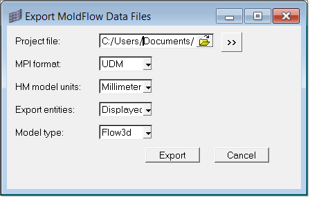
This dialog helps you to export the model and create the .udm file, which can be imported into Moldflow and solved.
|