|
»Click here to display Table of Contents«
|

Solid Meshing Wizard |

|

|

|

|
|
Solid Meshing Wizard |
|
|

|

|
|
»Click here to display Table of Contents«
|
Solid Meshing Wizard |
|
|
|
|
|
Solid Meshing Wizard |
|
|
|
|
The Solid Meshing Wizard creates solid (3D) mesh model data decks for injection molding analysis starting from solids. It enables meshing of solids using three different techniques:
| • | Solid map |
| • | Volume tetmesh |
| • | CFD Tetmesh (tetrahedral mesh with boundary layer) |
Mesh created in each solid is placed in a component collector with the name <Comp Name>_<3D Mesh type>#n, where <3DMeshtype> is either of the solidmap, tetmesh or BLmesh and n is an integer represents the ID of the respective solid in the model.
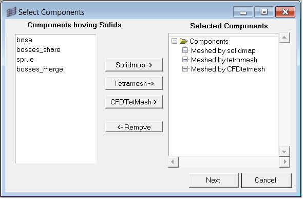
When you click on the Solid Meshing Wizard macro, it opens the following dialog. Select the components for meshing, and add it to the respective meshing group. For example, select base and click Solidmap to add it to the Meshed by Solidmap folder.
After selecting the components, click on Next to proceed.
|
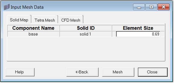
This panel shows three tabs, once corresponding to each meshing method. Solid Map and Tetra Mesh tabs list the selected components and respective solids with their IDs. It also shows the recommended element size for each solid as shown in the below image. This size can be edited.
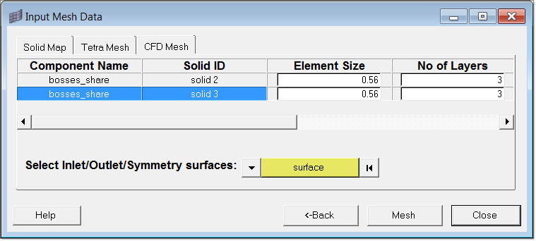
The CFD Mesh tab will display additional meshing parameters relevant to creating boundary layer mesh in addition to the element size, as shown in the below image. Please refer to the help on CFD BL meshing.
Use this tab to select and specify the surfaces to be considered as inlet/outlet/symmetry surfaces for the purpose of creating a boundary layer mesh. Refer to the CFD mesh help for better understanding of the above mesh parameters. Complete the mesh by clicking Mesh.
|