Orient Bar2 Elements
Use the Stiffener Mesh: Orient tool to define bar2 orientation vectors or orientation nodes.
There are two kinds of orientation vectors: Global and Basic. Global is used for displacement systems (or analysis). Basic is the HyperMesh global system (where system ID = 0).
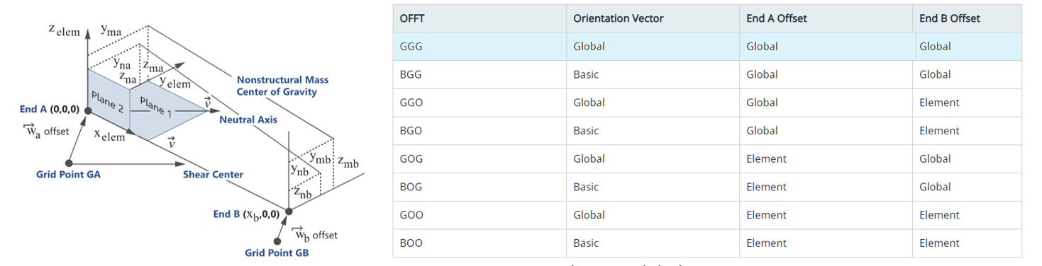
Figure 1.
-
From the Marine ribbon, click the tool.

Figure 2. - Optional:
On the guide bar, click
 to define orientation options.
-
To orient using a vector:
- Activate the By Vector checkbox.
- Use the options in the microdialog to orient.
Option Description Orient Beam/Bar as Plate Stiffener Click  to align the beam/bar
axis along the positive normal of an adjacent shell.
to align the beam/bar
axis along the positive normal of an adjacent shell.Normals of adjacent shells are averaged since they do not have an angle greater than the threshold value (break angle) defined in the options. For sharp angles, the shell with the lowest ID is used as a reference. In the case of T-junctions, you can select a reference shell by hiding undesired shells and by setting the "Normal from shells" option to Displayed.
Rotate Elements Along the X-Axis  - orient 90 degrees
clockwise
- orient 90 degrees
clockwise - orient 90 degrees
counterclockwise
- orient 90 degrees
counterclockwise - dynamically rotate
using a manipualtor
- dynamically rotate
using a manipualtorVector Tool and Systems Provide an arbitrary orientation vector in space using the Vector tool. - Click
 .
. - Orient the vector then press Esc to return to the current context.
- To select in which system the orientation vector component
is resolved, click
 in the Orient microdialog.
- System - Select a pre-defined system using an entity selector.
- Basic System - Place all X, Y, and Z components in the output system of beam node A.
Orient Bar2 Elements from Lines
Use the Stiffener Mesh: Orient tool to define the bar2 orientation vectors from selected lines.
This context differs slightly from 1D Mesh: Orient in that it not only enables the selection of elements but also enables free lines as a source.
When the selector type is free lines, 3D visualization for elements is turned OFF. The selection of lines will result in 1D elements found matching the line by proximity. 1D elements selection is resolved only on proceed, so there is no highlighting of elements from the selected lines.
-
From the Marine ribbon, click the tool.
Figure 3. - Optional:
Set options as necessary by clicking
 on the guide bar.