Extract Midsurfaces
Use the Midsurfaces: Automatic tool to extract the midsurface of sheet metal stampings, molded plastic parts with ribs, and other parts that have thickness clearly smaller than width and length.
-
From the Geometry ribbon, click the tool.

Figure 1. - Optional:
On the guide bar, click
 to define midsurface options.
Midsurface Method Options
The following methods are available when extracting the midsurfaces of thin solids.
Access this option by clicking ![]() on
the guide bar.
on
the guide bar.
- Planes + Sweeps + Offsets
- Identify the places where a piece of plane or a piece of a sweep surface
can be used as a middle surface. A middle surface is constructed at the
remaining places in the model, for example the places where planar or
sweep surface pieces cannot be used as a middle surface, by the same
algorithm as in offset via the offset of the model's sides.
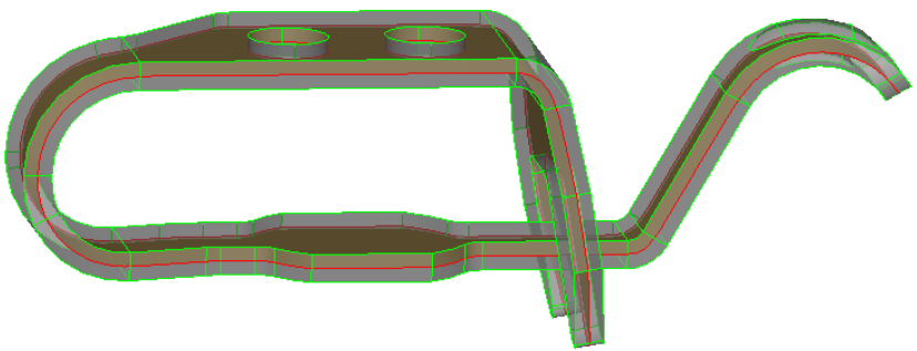
Figure 2. - Planes + Offsets
- Identify the places in the model where a piece of plane can be used as a
middle surface. At the remaining places in the model, for example the
places where planar pieces cannot be used as a middle surface, the same
algorithm as in Offsets is used to construct the middle surface via the
offset of the model's sides.
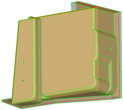
Figure 3. - Offsets
- Create pieces of the middle surface by offsetting the model's side
surfaces towards the middle. This is the traditional approach for
midsurfacing in HyperWorks.
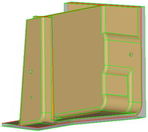
Figure 4. - Skin Offset
- Automatically detects the two largest faces on the model, detects the thickness, and then creates the middle surface by offseting one of the faces towards the other one by half of thickness. This is the quickest method for creating a midsurface. However, it is not applicable to many models.
- The typical models where "skin offset" can be successfully applied are
metal stamped parts.
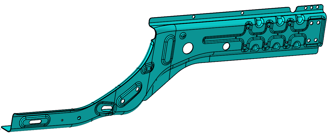
Figure 5.