Create and Edit Polylines
Use the Create Polylines tool to draw polylines for geometry construction and to generate meaningful snap locations to be used by other tools.
New lines are organized in the same component as the entity where the first end point is placed.
-
From the Geometry ribbon, Lines
tool group, click the Create Polylines tool.

Figure 1. - Optional:
On the guide bar, click
 to define controlled line
creation.
This creates controlled lines between locations with the possibility of reducing the number of joints and locations that fall outside the path line.
to define controlled line
creation.
This creates controlled lines between locations with the possibility of reducing the number of joints and locations that fall outside the path line. -
On the guide bar, click one of the following:
 - Save changes and stay in the tool
 - Save changes and close the tool
 - Exit the tool without saving changes
Controlled Line Creation Options
- Break Angle
- Specify the minimum angle allowed between three points in a line. If the angle between a point and the two adjacent points is less than the angle specified, this point is considered to be a point of discontinuity in the line and a joint is placed at that point.
- In the image below, a break angle is set to 150 degrees. The highlighted
point angle is closed to 135 degrees. Therefore, a joint is created.
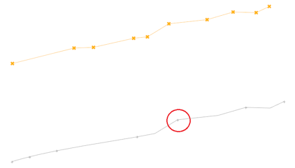
Figure 2. - Aspect Ratio
- Specify the maximum ratio allowed for the distance between a point and the previous point on the line, and the distance between the same point and the next point on the line. If the ratio of the distance between the two adjacent segments exceeds the defined aspect ratio, a joint is placed between the segments.
- In the image below, the aspect is set to 5. The large gap (top line)
results in a joint (bottom line) because it is more than 5 times the
length of its neighbors.
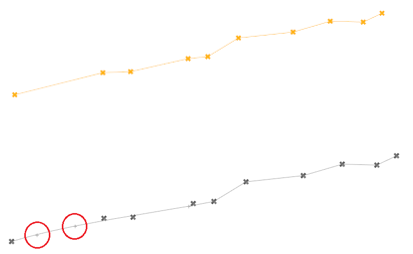
Figure 3. - Linear Angle
- Defines the angle at which a line is considered a straight line. If the line angle between three consecutive points along the line is greater than the angle specified, the center point is removed from the line.
- In the image below, three points (top line) are removed because they
form lines with their neighbors that are greater than the linear angle
setting.
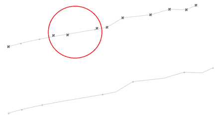
Figure 4.