Creates hexa elements between shell and/or solid elements in order to connect them using
a tie contact definition. The hexa element nodes will project and touch the shell and/or
solid element faces. During the realization, a default tie contact and referencing main
and secondary sets are created; unless defined differently, the hexas are assigned a
default property and material, and are organized into a component with the same name
base as the property.
The default tie contact and material parameters can be changed in the files below this
path: ..\Altair\2021\hwdektop\hm\scripts\connectors\Hexa_Tie\.
Note: IDs, names, and card
type cannot be changed.
Figure 1.
Hexa Realization Options
Option
Action
coats
Defines the number of hexa elements required along the
thickness.
Note: Multiple
solid coats are supported when adhesive-hemming is
selected.
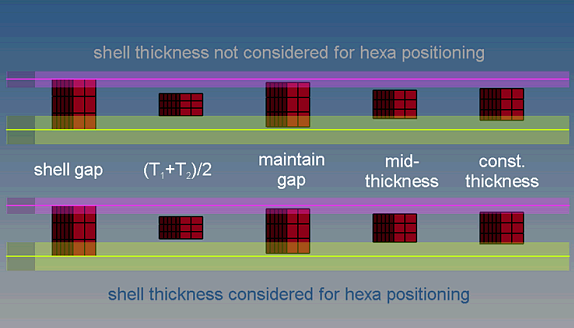
thickness
Select a method for defining the thickness of a hexa
weld.
shell gap
Project the hexa to touch the shell elements.
The position is independent from any thickness.
(T1+T2)/2
Hexa size (thickness) depends on the shell thickness of the connected
parts.
mid thickness
Calculate the hexa size (thickness) as the air gap between the two
connected parts.
If there is no gap, or even a penetration, the hexa size is always
modeled with 1.0.
const. thickness
Specify the hexa size (thickness).
maintain gaps
Calculate the hexa size (thickness) as the gap distance reduced by two
times the specified value for maintain gaps.
The position is independent from any thickness.
Note: The exact hexa position is also influenced by
the option consider shell thickness and offset for hexa
positioning.