User Defined Coordinate Systems

The User Defined System dialog allows you to define your own coordinate systems and use them for post processing results.

User defined systems can be broadly categorized as Fixed or Moving. In the case of transient animation, Fixed systems remain static and do not update with deformation, whereas Moving systems update with deformation.

Within each category, user defined systems can be Rectangular, Spherical or Cylindrical type.
Tip: Moving systems can also be used as Tracking Systems.
Note:
  1. Moving systems are not supported in the HyperView-Upfront Data Loading mode at this time.
  2. Systems from an input deck will be read as Fixed systems irrespective of how it is defined in the input deck.

The user defined systems can be saved to a session file or report template. In the case of a Fixed system, only the x, y, z coordinates of the origin and the three direction cosine vectors for the orientation are saved to a session file. In the case of a Moving system, the move type and node locators are also saved.

From the Create tools, click Systems.


Figure 1.
Note: You can also right-click within the Results Browser and select Create > System from the context menu.


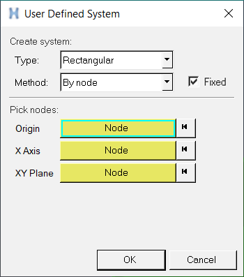
Figure 2. User Defined System dialog

If your model contains user defined systems, you can right-click on one of the existing systems in the Results Browser and select Create > System, Edit, or Delete, from the context menu.

Create a User Defined Coordinate System By Node

  1. From the User Defined System dialog, select one of the available coordinate systems.
    • Rectangular (X, Y, Z)
    • Cylindrical (R-Theta-Z)
    • Spherical (R-Theta-Phi)
    You are able to make changes to the coordinate system Type (Rectangular, Cylindrical, Spherical) after it has been created, however once a system exists you are no longer able to make changes to the location of the coordinate system.
  2. For Method, select By node.
  3. Choose a system category: activate the check box for Fixed or uncheck the box for Moving.
  4. Under Pick nodes, specify a minimum of three nodes to define the orientation of the system.
    HyperView will automatically provide the x, y, z positions (coordinates) of the nodes at the time of definition. For the Linear or Modal animation modes, the undeformed position (model location) of nodes is considered in defining the system. For the Transient animation mode, the deformed position (current location at the time step) is considered.
    Note: Scaling does not affect the position of the nodes/points. The unscaled coordinates of the current node/point positions are used when defining nodes/points.
    1. Click the Origin input collector and use the Select by ID dialog to specify your desired nodes.
    2. Click the X Axis input collector and use the Select by ID dialog to specify your desired nodes.
    3. Click the XY Plane input collector and use the Select by ID dialog to specify your desired nodes.
  5. Click OK to apply the settings/changes and exit the dialog.

Create a User Defined Coordinate System By Circle Center

All user defined coordinate systems are static (or fixed).
  1. From the User Defined System dialog, select one of the available coordinate systems.
    • Rectangular (X, Y, Z)
    • Cylindrical (R-Theta-Z)
    • Spherical (R-Theta-Phi)
    You are able to make changes to the coordinate system Type (Rectangular, Cylindrical, Spherical) after it has been created, however once a system exists you are no longer able to make changes to the location of the coordinate system.
  2. For Method, select Circle center.
  3. Choose a system category: activate the check box for Fixed or uncheck the box for Moving.
  4. Under Pick 3 circle circumference nodes, specify three nodes lying on the circumference of the circle to define a coordinate system at the circle center.
    The origin of the system will be the circle center, and the x-axis of the system will defined along the vector between the circle center and the first selected node.
    Note: If a circle center could not be computed using the three selected nodes (for example collinear nodes), or, if the computed circle center, Node1, Node2 are collinear, then a default system will be created. The axes of this default system will align along the global axes.
    1. Click the Node 1 input collector and use the Select by ID dialog to specify your desired nodes.
    2. Click the Node 2 input collector and use the Select by ID dialog to specify your desired nodes.
    3. Click the Node 3 input collector and use the Select by ID dialog to specify your desired nodes.
  5. Click OK to apply the settings/changes and exit the dialog.

Create a User Defined Coordinate System By Coordinates

All user defined coordinate systems are static (or fixed).
  1. From the User Defined System dialog, select one of the available coordinate systems.
    • Rectangular (X, Y, Z)
    • Cylindrical (R-Theta-Z)
    • Spherical (R-Theta-Phi)
    You are able to make changes to the coordinate system Type (Rectangular, Cylindrical, Spherical) after it has been created, however once a system exists you are no longer able to make changes to the location of the coordinate system.
  2. For Method, select By coordinates.
  3. Choose a system category: activate the check box for Fixed or uncheck the box for Moving.
  4. Under Enter Co-ordinates, specify three nodes to define the orientation of the system.
    1. Define the Origin of the system.
    2. Define the local X-Axis (or R-Axis for Cylindrical or Spherical systems).
    3. Define the X-Y Plane (or the R-Theta Plane for Cylindrical or Spherical systems).
  5. Click OK to apply the settings/changes and exit the dialog.

Edit a User Defined Coordinate System

Use the User Defined System dialog to review and edit (or redefine) user defined coordinate systems.
  1. From the Results Browser, right-click on one of the existing systems and select Edit from the context menu.
    Restriction: Only user defined coordinate systems can be modified or deleted. Coordinate systems from the input deck cannot be modified or deleted, they can only be reviewed.
    The User Defined System dialog is displayed.
  2. Edit or modify the definition of the system by changing the system 'type' or redefine the system by selecting new nodes.
    Note: The coordinates are not retained.
    The coordinates of the nodes are internally updated whenever you update the node IDs.
    • You therefore do not need to remember the node IDs, only their positions at the time of creation/updating of the Coordinate System is modified.
    • To modify the coordinate system, you simply need to provide new node IDs. New node IDs automatically get converted to x, y, z positions.

    No scaling of deformation contributes to the changing of position of the nodes. Unscaled node coordinates at the time of Coordinate System creation are used.

  3. Click OK to apply the settings/changes and exit the dialog.

Delete a User Defined Coordinate System

From the Results Browser, right-click on one of the existing systems and select Delete from the context menu.
Note: Only user defined coordinate systems can be modified or deleted. Coordinate systems from the input deck cannot be modified or deleted, they can only be reviewed.