HyperView Coordinate Systems
In the Contour, Iso Value, Tensor Plot, Vector Plot, and Deformed panels, you can select the result coordinate system to be used to process results.
Subsequent options are dependent on the current averaging method. The available coordinate systems are:
Global
The HyperView default coordinate system. It is displayed in the bottom left corner of the HyperView modeling window.Element
Defined from the geometry, that is, the nodal connectivity of the element. The HyperView element coordinate systems for the following elements are described:- Quad4/Quad8
- For Quad elements, the reader automatically selects one of the following methods:
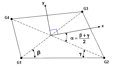
Figure 1. Method 1- The origin of the coordinate system is located at the centroid of the element.
- x is along a line that bisects the angles between G2-G4 and G1-G3.
- y is perpendicular to x as shown in the figure.
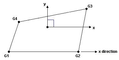
Figure 2. Method 2- The origin of the coordinate system is located at the centroid of the element.
- x is along the G1-G2 line.
- y is perpendicular to x.
- Tria3/Tria6
-
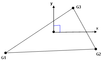
Figure 3.- The origin of the coordinate system is located at the centroid of the element.
- x is along the G1-G2 line.
- y is perpendicular to x as shown in the figure.
- Hexa8/Hexa20
- The element coordinate system for the Hexa element is defined in terms of the three
vectors R, S, and T, which join the centroids of opposite faces, as follows:
- R vector joins the centroids of faces G4-G1-G5-G8 and G3-G2-G6-G7.
- S vector joins the centroids of faces G1-G2-G6-G5 and G4-G3-G7-G8.
- T vector joins the centroids of faces G1-G2-G3-G4 and G5-G6-G7-G8.
The origin of the coordinate system is located at the centroid of the element. The axes are derived as follows:- z = T
- y = T x R
- x = y x z
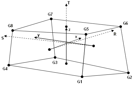
Figure 4. - Tetra
- The element coordinate system is derived from the three vectors, R, S, and T, which
join the midpoints of opposite edges, as follows:
- R vector joins midpoints of edges G1-G2 and G3-G4.
- S vector joins midpoints of edges G1-G3 and G2-G4.
- T vector joins midpoints of edges G1-G4 and G2-G3.
The origin of the coordinate system is located at the centroid of the element. The axes are derived as follows:- z = T
- y = T x R
- x = y x z
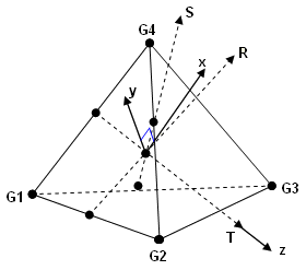
Figure 5. - Penta
- The element coordinate system for the Penta element is derived accordingly. A midplane
is formed by the three midpoints of the straight lines between the top (G1-G2-G3) and
bottom (G4-G5-G6) triangular faces. The origin of the coordinate system is located at
the centroid of the element. The axes are formed as follows:
- z = A line along the bisector of the midplane normal and the line connecting the centroids of the top (G1-G2-G3) and bottom (G4-G5-G6) faces.
- y = The vector connecting points P and Q where P and Q are defined as
follows:
P = The midpoint along the line, G1-G4. In order to define Q, you must define a plane that passes through P and is perpendicular to axis z.
Q = The intersection of the plane defined above and the line G3-G6. - x = The intersection of the plane defined above and the line G3-G6.
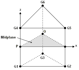
Figure 6.
Material
Transforms to the material system.Note: This option is only available when the Advanced Result Math template is
selected in the Load Model panel and a solver input deck is loaded.
Ply
Transforms to the ply system.Note: This option is only available when the Advanced Result Math template is
selected in the Load Model panel and a solver input deck is loaded.