Create Iso Surfaces for Nodal Results

  1. From the View Controls toolbar, click .
  2. From the Iso panel, select the data type that should be used to calculate the iso values from the Result type drop-down menu.
    The available result types change depending on the result file that is loaded.
    Each result type is followed by a letter that indicates the category to which it belongs. (t) indicates a tensor-type result, such as stress or strain tensors. (v) indicates a vector-type result, such as displacement, velocity, and acceleration. (s) indicates a scalar-type result. (c) indicates complex results.
    Tip: Click the expansion button to open the Choose From List dialog, where you can filter result types for faster selection.
  3. Select a data component type from the second drop-down menu in the result type section.
    The list of available components is based on the selected result type. For example:
    Result type Component options
    Displacement (v) Mag, X, Y, or Z.
    Stress (t) vonMises, Signed vonMises, P1(major), P2(mid), P3(minor), Pressure, MaxShear, Intensity, In-plane P1(major), In-plane P2(minor), XX, YY, ZZ, XY, YZ, or ZX.
    1D stress Multiple options are listed for various elements such as: CELAS, CROD, CBAR, CBEAM, etc
    Energy (s) No component selection is necessary.
  4. Before creating an iso plot, you may pick one or more entities from the model.
    • Click the Components input collector and use the extended entity selection menu.
    • Pick entities directly from the model in the modeling window.
    Note: If no selection is made, the iso plot will be applied to displayed components by default.
    For iso or multiple models, see Multi-model Result Plotting for additional information.
    Component selection restricts the iso surface to the selected parts only, while displaying the rest of the geometry which needs to be displayed in full. In most of the CFD applications, the fluid elements need to be iso surfaced, with the structural parts displayed as a whole. The figure below shows a pump impeller geometry, with the iso surface on the fluid elements based on pressure data. The contour shown is velocity of the fluid as it is displaced by the impeller blade.
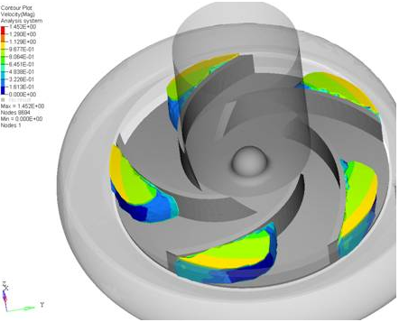

    Figure 1.
    When performing ALE simulations in Radioss, or other solvers, of fuel tank sloshing or ditching of an airplane, the iso surface of density on selected components (the mesh representing the fluid) helps visualize the interaction of the fluid with the structure. The image below shows a ditching simulation of an airplane in water. The airplane block is investigated while the density iso surface is applied only on the fluid to show the water displacement due to ditching.
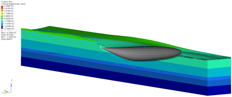

    Figure 2.
  5. Select the coordinate system that will be used to calculate the results from the Resolved in drop-down menu.
    Coordinate System Description
    Global System Transforms to the global system.

    proj: none indicates that no projection rule is selected for shells. If a projection rule is selected (using the Projection Rule button) it will be displayed.

    Elemental System Transforms results to the element coordinate system. In HyperView, the element coordinate system is defined by element connectivity.
    Material System Transforms to the material system.
    Note: This option is only available when the Advanced Result Math template is selected in the Load Model panel and a solver input deck is loaded.

    For plotting data types that do not have relevance to the Material system (for example, Stress with a Z1 and a Z2 data type), it is not advised that you apply the Resolved-In system of Material, because this may result in incorrect transformations.

    Ply System Transforms to the ply system.
    Note: This option is only available when the Advanced Result Math template is selected in the Load Model panel and a solver input deck is loaded.

    For plotting data types that do not have relevance to the Ply system (for example, Stress with a Z1 and a Z2 data type), it is not advised that you apply the Resolved-In system of Ply, because this may result in incorrect transformations.

    Analysis System Displays the vector and tensor results as they are output from the solver.
    User System Click the System input collector to select a system by ID or pick from the screen.
    Note: This option is available when the results file contains a user-defined coordinate system.

    proj: none indicates that no projection rule is selected for shells. If a projection rule is selected in the Projection Rule dialog, it will be displayed next to the User System option.

  6. Click Apply.
    The selected options are applied and the model is displayed in iso value mode.