The Free Body Diagram (FBD) tool facilitates the extraction and post-processing of Grid
Point Force (GPFORCE) results and can be used create and edit Free Body Diagrams
(FBD).
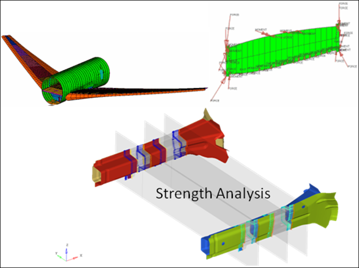
FBD extractions are typically utilized for breakout and/or
sub-modeling analysis schemes, where balanced "free body" sub-cases are extracted from a
coarse grid model and applied to a fine grid sub-model for eventual optimization and/or
analysis. FBD is also used to extract section resultant forces and moments (typically at the
centroid of a section) for use in traditional strength calculations. Figure 1.
FBD Utility
The FBD utility extracts grid point
force data (including forces and moments) for a user-defined element set and is useful for
doing breakout modeling within a sub-modeling scheme. Results can be output for graphical
review, a text summary table, and/or a formatted Comma-Separated Values
(.csv) file which can be loaded into traditional spreadsheet software
packages.
The data from the currently loaded model/results file and the selected load
case/simulation in the Results browser will be used for all grid point force based
calculations. The FBD utility currently supports ANSYS (Rst),
Nastran (Op2/XDB), OptiStruct
(Op2), Abaqus (ODB), and H3D result files.
Note: The following
data types must be present in the result file to launch and use the FBD tool:
ANSYS: "Element Nodal Force as Vector" and "Element
Nodal Moment as Vector"
Nastran/OptiStruct: "Grid
Point Element Forces" and "Grid Point Element Moments"
In the case of OptiStruct H3D, make sure that
GPFORCE(FBD) is requested for output when setting up the analysis.
Abaqus: NFORC Forces/Moments
Important: The Advanced Result Math template must be selected when
loading the model and result files in the Load Model panel.
From the Query tools,
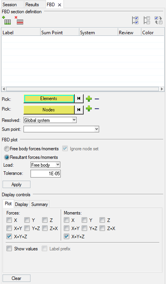
click the FBD tool. Figure 2.
Figure 3.
The FBD Forces utility is displayed in the tab area and is broken down into three major
sections, each of which corresponds with the process order of using the tool:
FBD section definition
Element based sections are defined and modified in this first step of the process.
You can define multiple sections, associate elements, associate a node group (optional
for resultant summation), or define other attributes (like a summation point, a
coordinate system, etc.).
FBD plot
Once the sections are defined, you can plot results (Freebody or Resultant
Forces/Moments) in this middle step of the process.
Display controls
The presentation of the results/plots are controlled in this final step of the
process. The various controls allow you to determine how the vectors are drawn in the
modeling window, view the results in a summary table, or
export/save the results to a .csv or .fbd
file.