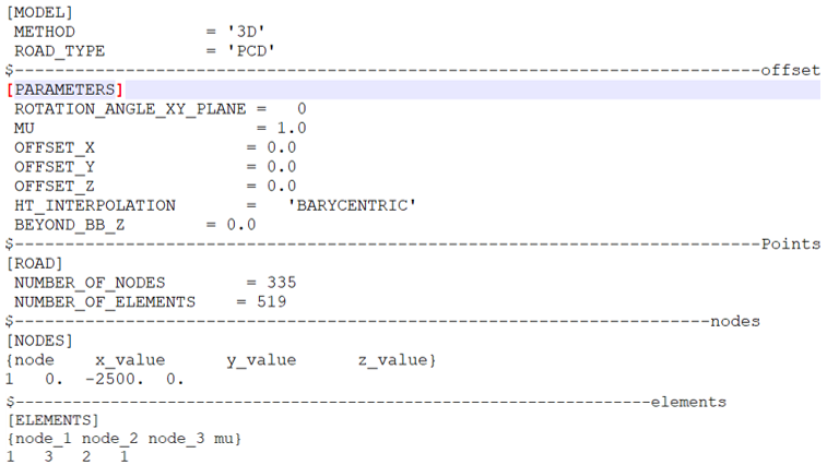
Roads whose data is represented in the form of surface
elements made of triangles can be termed as 3D Shell road or Triangulated road or Tesselated
road surface. The keyword used for indicating this road type to MotionSolve is PCD. PCD stands
for point cloud data. Figure 1. 3D Shell
Road Data Format
The road surface data is given in the form of two tables NODES and ELEMENTS.
The NODES table consists of four columns. Column1 being the node number/node count. Nodes
are vertices. column2, column3 and column4 being x, y, z coordinate of the vertices of the
triangle element.
The ELEMENTS table consists of four columns. Column1, column2 and column3 being the node ID
of the vertices making up the triangle element. Column4 contains the coefficient of friction
of the particular element. This information is not used by the software currently.
A rdf file containing the above mentioned road data along with some additional information
as required by the MotionSolve has to be provided. They are as follows:
UNITS block
MODEL block containing:
Method as 3D
and
ROAD_Type as PCD
ROAD block containing the information about the triangles is road surface:
NUMBER_OF_NODES
and
NUMBER_OF_ELEMENTS
An optional PARAMETERS block containing the following:
OFFSET_ X: x coordinate of origin.
OFFSET_ Y: y coordinate of origin.
OFFSET_ Z: z coordinate of origin.
HT_INTERPOLATION: The interpolation method used to get the height at contact
patch. Available methods:
BARYCENTRIC: weighted average of CP height with regard to its position in the
triangle.
LINEAR: Average of the height at the vertices of the triangle.
BEYOND_BB_Z: Height to be used outside the bounding box of the road.
The ROTATION_ANGLE_XY_PLANE can be used to rotate the road on top of the road
reference marker.
Figure 2. rdf File
If the tire is inside the biggest bounding box of the road but is outside the road patch,
the previously seen height will be used.
Best Practices
To get the full advantage of the triangulated road it is advised to perform the
following:
If the vehicle is kept on an uneven or a slant surface at the beginning, MotionSolve
will have difficulties in obtaining a static equilibrium for the tire. It is advised to
place the vehicle on a flat surface if such a problem occurs.
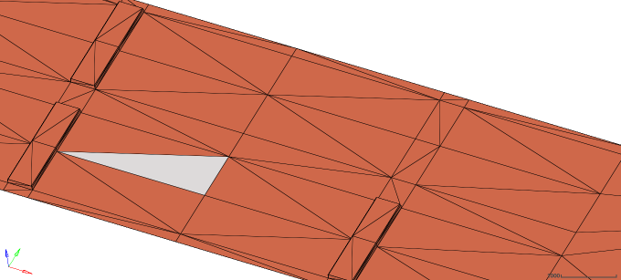
Have as big elements as possible on flat surfaces.
Use smaller elements only to capture the curvature of geometry. Figure 3. Big elements for flat surfaces and smaller elements for capturing
curvature
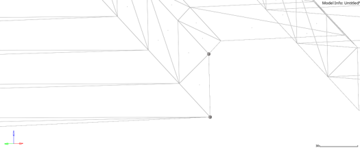
Try to avoid exactly vertical elements where there are nodes lying on the same x,y
point. Instead try to provide a small difference in the bottom and top nodes like
0.001m. Figure 4. Avoid exactly vertical nodes as shown