3D Spline Road
The 3D Spline Road allows racetracks, parking spaces and various other 3-Dimensional smooth road surfaces, to be defined. When a road surface, with a curvature less than that of the tire is present, it is defined as a smooth road.
Additionally, the 3D Spline Road allows you to model 3-Dimensional road obstacles, placed atop the underlying smooth road surface. The centerline, width, bank angle, and left and right friction levels define the road surface.
Coordinates of the road centerline can be specified by to construct any line in 3-Dimensional space. A flat cross-section is assumed, for which the width and bank angle can be specified for each data point. Additionally, friction levels for left and right road sides can be specified.
3D Spline Road Obstacle Types
- POTHOLE
- RAMP
- PLANK
- ROOF
- SINE
- SWEEP
Placing an Obstacle
The obstacles are based on “distance travelled “ methodology. The keyword START in each obstacle tells the relative distance of start of the obstacle to the spline’s coordinate where it is mentioned in the table. So by mentioning 0 it means the obstacle starts immediately. In the attached 3D spline road sample OBSTACLE1 starts at x,y = 5,0 as its START value is 0.Keywords
- Global Keywords
- The keywords which are required for all obstacles are:
Keyword Description START The start position of the obstacle. - '0.0 0.0 0.0'
- A local coordinate system.
- '0.0'
- A distance-defined obstacle.
LENGTH The length of the obstacle. LENGTH is to be defined along the length of the road.
ROAD_TYPE The obstacle type. Note: The above data must be specified in the .rdf file, independent of the type of obstacle.
- POTHOLE
- A single pothole of rectangular shape.
If ROAD_TYPE = 'POTHOLE', then the 'DEPTH' keyword must be specified. Depth can be positive indicating a depression or negative indicating a bump in the road.
Add a table for pothole like the one below with corresponding terms:Keyword Description DEPTH Positive / negative depth of the obstacle. 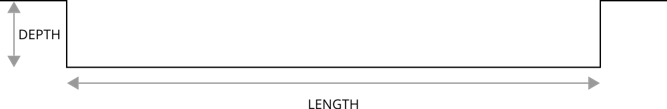
Figure 1. Pothole Illustration - RAMP
- A single ramp, either rising or falling.If ROAD_TYPE = 'RAMP', then the following parameters must be specified:
Keyword Description HEIGHT Height of the ramp. SLOPE Slope of ramp in deg(°). 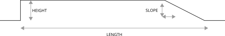
Figure 2. Ramp Illustration - PLANK
- A single plank perpendicular, or in oblique direction relative to x-axis, with or
without bevel edges.If ROAD_TYPE = 'PLANK', then the following parameters must be specified:
Keyword Description HEIGHT Height of the plank. BEVEL_EDGE_LENGTH BEVEL_EDGE_LENGTH < 0, 3D Spline Road uses rounded corners instead of beveled edges. In this case, the radius of the corner is BEVEL_EDGE_LENGTH. 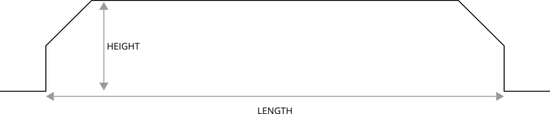
Figure 3. Edged Plank Illustration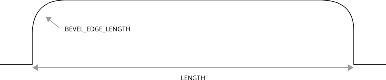
Figure 4. Rounded Plank Illustration - ROOF
- A single roof-shaped, triangular obstacle.If ROAD_TYPE = 'ROOF', then the following parameters must be specified:
Keyword Description HEIGHT Height of the roof. LENGTH Length of the base of the triangular roof. 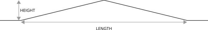
Figure 5. Roof Illustration - SINE
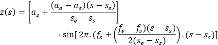
- Sine waves with constant wave length.If ROAD_TYPE = 'SINE', then the following parameters must be specified:
Keyword Description AMPLITUDE Amplitude of the sine wave (A). WAVE_LENGTH Wave length of the sine wave (  ).
).START Start of the sine waves (travel distance) (s_s). The road profile height z, is given by:
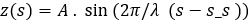
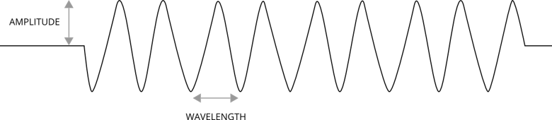
Figure 6. Sine Illustration - SWEEP
- If ROAD_TYPE = 'SWEEP', then the following parameters must be specified:
Keyword Description AMPLITUDE_AT_START Amplitude of the sine wave at start (  )
)AMPLITUDE_AT_END Amplitude of the sine wave at end (  )
)WAVE_LENGTH_AT_START Wave length of the sine wave at start (  ).
).WAVE_LENGTH_AT_END Wave length of the sine wave at end (  ).
).SWEEP_TYPE If SWEEP_TYPE = 0, then the frequency changes linearly. If SWEEP_TYPE = 1, then the frequency changes logarithmically.
Depending on the value of SWEEP_TYPE, the road profile height is given by the following functions:- Linear Sweep
- The frequency changes linearly with distance
s. The road profile height z is
given by:
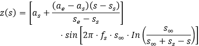
- Logarithmic Sweep
- With every cycle, the wavelength decreases by a constant factor.
The road profile is given by:
where,
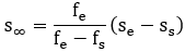
 is the distance at which,
theoretically, an infinitely high frequency is reached, with
respect to the start ss.
is the distance at which,
theoretically, an infinitely high frequency is reached, with
respect to the start ss.
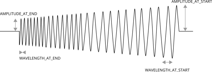
Figure 7. Sweep Illustration
3D Spline Road Property File
- MDI_HEADER
- The first block of data [MDI_HEADER] describes the TeimOrbit
file:
[MDI_HEADER]
FILE_TYPE = 'rdf'
FILE_VERSION = 5.00
FILE_FORMAT = 'ASCII'
{COMMENTS}
'User entered comments go here'
Keyword Description FILE_TYPE The file type. FILE_VERSION The version of file; to be changed when modifications to this file are made. FILE_FORMAT The format of the data; for TiemOrbit this is always ASCII. {COMMENTS} Descriptive comments about the file, such as what road this represents, when the data was acquired, etc. - Units details
- The [UNITS] block defines the units for the
road:
[UNITS] LENGTH = 'meter' FORCE = 'newton' ANGLE = 'radians' MASS = 'kg' TIME = 'sec'[UNITS]Keyword Description LENGTH Unit of length. FORCE Unit of force. ANGLE Angle in degrees or radians. MASS Unit of mass. TIME Unit of time. - Model details
- The [MODEL] block defines the road model and version for the
road:
[MODEL] METHOD = '3D_SPLINE' VERSION = 1.00[MODEL]Keyword Description METHOD 3D_SPLINE - Global Parameters
- The [GLOBAL_PARAMETERS] block defines parameters applicable to the entire
road:
[GLOBAL_PARAMETERS] CLOSED_ROAD = 'NO' SEARCH_ALGORITHM = 'FAST' ROAD_VERTICAL = '0.0 0.0 1.0' FORWARD_DIR = 'NORMAL' MU_LEFT = 0.5 MU_RIGHT = 0.6 WIDTH = 5.000 BANK = 0.0[GLOBAL_PARAMETERS]Keyword Description CLOSED_ROAD Whether the road is closed or open. - YES
- The road is closed.
- NO
- The road is open.
FORWARD_DIR Forward direction of the road: - NORMAL
- Vehicle travels along the specification of road data point.
- INVERT
- Vehicle travels in a direction opposite to that of specified road data points.
MU_LEFT Road friction value on the left side of the road with respect to the centerline. Specifying road friction under [GLOBAL_PARAMETERS] overwrites any specification of road friction values in the [DATA_POINTS] block. MU_RIGHT Road friction value on the right side of the road with respect to the centerline. Specifying road friction under [GLOBAL_PARAMETERS] overwrites any specification of road friction values in the [DATA_POINTS] block.
WIDTH Width of the road. If user specifies WIDTH, it takes precedence over the WIDTH value specified in the [DATA_POINTS] block. Even if this parameter is set, user must specify the WIDTH parameter in [DATA_POINTS]. If this parameter is not required, then user can omit it from the road data file (.rdf).
BANK Slope angle of the road around its centerline in each data point. Zero bank means a horizontal width line. A positive value specifies a slope along a clockwise direction in ISO-reference frame.
If you specify this dimension, then it will take precedence over the BANK value specified in the [DATA_POINTS] block. Even if you set this dimension, they must specify a BANK value. If this dimension is not required, then you can omit it from the .rdf file.
- Data Points Information
- The [DATA_POINTS] block contains the road information in a tabular form.
The following information needs to be supplied for each entry:
[DATA_POINTS] { X Y Z WIDTH BANK MU_LEFT MU_RIGHT OBSTACLE}[DATA_POINTS]Keyword Description X The X coordinate of sampled road data point. Y The Y coordinate of sampled road data point. Z The Z coordinate of sampled road data point. WIDTH The width of road at the sampled point. BANK The angle of road at the sampled point; a positive value specifies a slope along a clockwise direction in ISO-reference frame. MU_LEFT Road friction on the left side of the road with respect to the centerline at the sample point. MU_RIGHT Road friction on the right side of the road with respect to the centerline at the sample point. OBSTACLE The name of block that contains the obstacle information. This entry is optional.